Just the one site to see today, on YouTube, and the background idea for a future layout design. Let’s away!
Site 1: Bacchus Marsh, Victoria
Whenever I travel to Melbourne on the train I pass through Bacchus Marsh (it’s around the halfway point between Ballarat and Melbourne). I recently found a new channel on YouTube featuring Trams and Trains from around Melbourne. Watching the operations in the video below at Bacchus Marsh led me to thinking about an exhibition layout. With the wealth of Ready to run (RTR) rolling stock available and the intensive working of the passenger service (especially the storage of train sets) this could have the makings of a great medium-sized exhibition layout.
First watch the video and then take a look at the signalling diagram below.
Video 1: V/Line Variety at Bacchus Marsh Railway Station in 2012
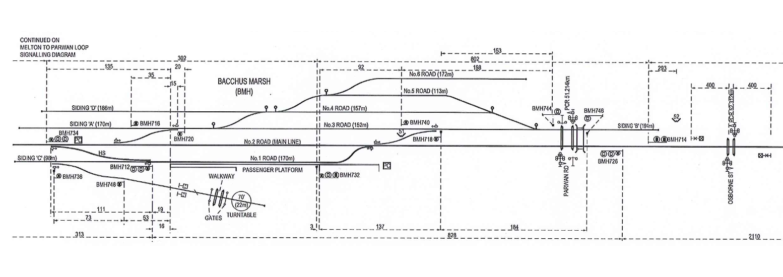
Image 1: The Bacchus Marsh signalling diagram & Tram layout
I think that there is plenty enough in the track layout to keep an exhibition crew going all weekend. With the station being both a single platform terminus and through platform (with the right hand side going through to Ballarat and beyond) this could be nirvana for DMU & Loco hauled railway modellers. Your thoughts?
I have toyed with track plans for some time to see how best to fit a layout into the current space that I have. I’ve drawn out 50 different track plans, all of which will fit my needs and space, none of which really grabbed me emotionally.
I took another look at a layout I’d designed early in 2014 last week. Designed to be portable and to be taken to exhibitions. In the space I gave it (8 feet or 2400 mm long) the design was right on the perfect size if for me just a little short of perfect. There is nothing wrong with the layout design or operations plan; it works exactly how I’d designed it to work and with the attached fiddle yard it will be a cracker of a layout to work for extended periods at an exhibition.
It will be:
Easy to work by one person,
Take about 30 minutes per show (operating session),
Allow short bursts of work, interspersed with periods of talking with the people asking questions about the layout), and
Worked from the front of the layout.
To get a sense of what I’m aiming for take a look at this video from Model Railroad Hobbyist:
MRH shot the video on Mike Confalone’s layout (I loved it so much I bought his video and book set – they are really worth their weight.) Watch the thing and you’ll be hooked.
Introspection
The layout is a fictional end of the line switching area. I’ve long been a fan of a little layout call Iota from a long ago RMC article. But while I wanted to make a larger version of the Iota, and have devised several track plans to do just that I’ve never been able to get it to work for me in my space.
I’d even thought about doing Box Car Haven (link here) as I have the space and boards ready to go. However, I wanted something simpler, with enough work operationally to allow me greater play time, and less staging and management.
Context
The fact that my location and layout is fictional means little to me. I have thought about the location, its history, and its present in-depth. There’ll be a sense of abandonment, growth, decline and then regrowth in the scenic treatment; buildings will also show this time of change on their surface, with old parts, and new construction giving the viewer a sense of time having passed.
The layout sits at a datum of 49 inches off the floor. This is about right for my son’s eye height at the moment. My wife and daughter are a couple of inches shorter than my son and so for now the layout stays where it is. I’d like to have the datum moved up to my eye height of 66 inches above the floor, but then no one else would enjoy the show.
I’ve designed lines of sight into the layout to stop people from being able to see the entire layout at any one time, and forcing them to move, change their viewing angle, look around corners and peer through building alleys into the layout.
The layout though small works on the principle of a two person crew. So even through the engineer cannot see the distances he has to go, his conductor is on the ground guiding him in – just as in the real world of railroading.
Physics
I’ve changed all the freight car bogies over to Kadee fully equalised trucks. Proto-weighted the cars to their cubed scale-weight equivalent, and weighted them heavy down low but glued weights along the tops of the cars in the corners to ensure that I’ll get a little rocking motion; it’s not perfect or quite how I’d like it but I cannot fully scale down the physics. In this way the cars move in a very prototypical fashion along the rails – especially Boxcars and Covered Hoppers.
During testing on the mocked up track plan I had a couple of months ago, the cars moved pretty much like you’d expect a real car to move. My switcher strained to get cars moving (so I’d get to feed power in to take up the slack) and then I could ease back on the throttle to keep them moving. In HO scale (I also model in O scale) you have no idea how sweet it is to see a switcher stretching a train and watching cars fight the move until inertia takes over. Once the load stretches out you have to drive the locomotive like the real thing.
The last thing on my list is to limit the speed of all loco decoders to around 25 MPH. And I’m going to drop the output level of the bell, and the sound decoder in general.
Additions
As a whole package the design will work, at least for me, to allow a simple and easy to set up switching session any night that I want to for around 30 minutes worth of fun. There’s little management time required and the fun starts with only a limited amount of set up time. There are additions I’ll be adding to the layout to extend the run around the second wall of the garage to extend the switching room and to lengthen the operation time to about the 60 – 75 minute mark for longer operating sessions.
Added to that the CV changes I’ve made to make sure that trains simply do not stop but roll on means that all along the way I’ll be happy working the model to give me and the other operators a sense of what it really means to work my layout.
Summary
Gritty, run-down, rebuilt and modernised, the Hunter Valley RR will be a lot of fun to run. I’ve got to spend some time working the track plan out in AnyRail over the next week. Once I have that completed I’ll post a copy here and see what you think.
Originally Posted on the Old HVL blog March 24, 2013
OK, so a little about the design and build of the layout boards.
In general all wood is fine quality pine dressed all round (DAR). The board top is 12 mm ply (1/2 inch), while the sky board is 6mm (1/4″) ply. THe legs are “L” girders using 1×2 and 1×3 DAR pine glued and screwed on the along their length. At the base of the leg is a glue bock of 2×1 DAR pine which is used to locate a T nut, with a 5/16″ bolt as a leveller. The nut for the 5/16th bolt mounts on the top of the glue block locking the bolt in place once you’ve levelled the board. I’ll be building a better foot arrangement at some point in the future that is easier on the floor, most likely a wooden ball with a 5/16″ nut through the centre of the wooden ball.
All of the side and end rails are 3 x 1 DAR pine and these have not been glued, but have been Kreg pocket screwed together. The ply was then glued and screwed to the box. Nice, tight and very rigid. There is one rail across the board in the centre of 2×1″ DAR pine, this has also been Kreg pocket screwed to the sides and the top was glued and screwed tothis also. The skyboard is glued and screwed to 1×2 pine DAR which acts as a stiffener and mounting point on the back of the main board. Mounting to the rear of the main boards is achieved using Kreg pocket screws.
The legs are mounted to the main board using 3 screws on each side to the sides. The top horizontal board bears the weight of the main board above; while the bottom horizontal board acts as a bearing face between boards and allows the boards to lock together using a wooden clamps from offcut of the hozontal boards and 1 x 2 DAR pine. Think an inverted U locking the two legs together. Nice, tight, simple and about 3 months in the planning.
Overall what are my impressions? Very happy to be over the hump of the work. The boards are light and strong. I can lift them fork lift style on my own without hurting myself and as I have a 50 year old back; this is a good thing. Thanks to my wife (Janette) for suggesting the mounting height for the sky boards. At 400mm above the plane of the board they are high enough to be at or just below my eye height, and with the 2×1 stiffeners behind allow easy mounting of lights that will hang out over the board for better simulation of daylight.
I’ve a few sketches and such to put on the gallery site later in the week. This should give you an idea of how the parts look. More photos will be coming before I paint everything later this month or during April, depending on the weather. Well a great day in all, now some remedial work on the old boards to bring them up to spec and height, and then my work is done.