Yesterday was all about passenger service; today is all about freight. Chris Gilbert pointed this video out, on his YouTube page. However the producer is ChicagoJoe28. But enough words let’s get to the video.
Site 1: Mike switches Batory Foods Chicago Terminal railroad
Video 1: Batory Food Switching on the Chicago Terminal
A little history
Located at 2234 W 43rd St, Chicago, IL 60609, Batory Foods began trading in 1979 when Abel Friedman opened Chicago Sweeteners. As a single source supplier of basic food ingredients such as sugar, flour, salt, starch, milk, oats, honey and corn syrup. Chicago Sweeteners expanded its product offering over time, as food manufacturers sought to develop healthier products.
With success in the greater Chicago market, the Company brought its broad line model to food manufacturing centres around the country. Some of the growth came with the original business; some by way of acquisition with:
Sugar Incentives bought in 1995,
Ingredients International in 2006,
Quality Ingredients in 2008,
LSI in 2009,
Industrial Ingredients in 2009,
Massey Fair in 2011, and
Mac Source in 2011.
Recently, the various names were consolidates into the single name: Batory Foods.
The layout idea
The site’s switched as an Inglenook. The two on-site spurs lead to undercover augers (I’m assuming here of course) for unloading powdered or granulated product.
The storage track goes to other industries further down the track, but does not show recent use from my quick look. The loco has to push the cars into the site so you have a simple, prototypical Inglenook that won’t take up too much space. It is small enough that you could model any date from 1979 on in HO, S or O scale.
SCORE! What are your thoughts?
Thanks to Chris Gilbert for the vision, and to ChicagoJoe28 for filming it.
Just the one site to see today, on YouTube, and the background idea for a future layout design. Let’s away!
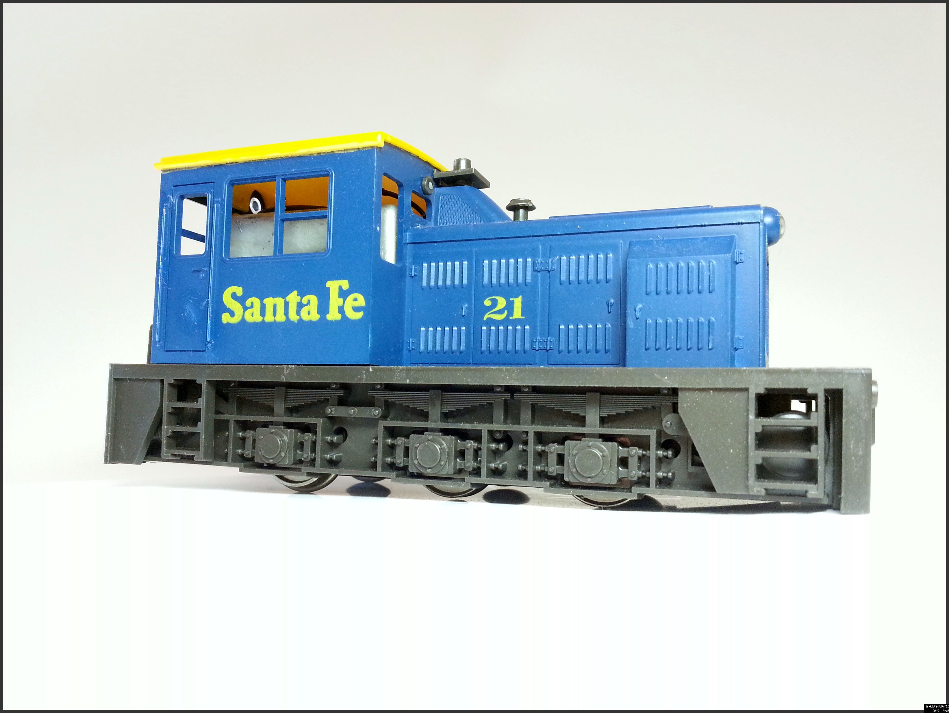
Site 1: Bacchus Marsh, Victoria
Whenever I travel to Melbourne on the train I pass through Bacchus Marsh (it’s around the halfway point between Ballarat and Melbourne). I recently found a new channel on YouTube featuring Trams and Trains from around Melbourne. Watching the operations in the video below at Bacchus Marsh led me to thinking about an exhibition layout. With the wealth of Ready to run (RTR) rolling stock available and the intensive working of the passenger service (especially the storage of train sets) this could have the makings of a great medium-sized exhibition layout.
First watch the video and then take a look at the signalling diagram below.
Video 1: V/Line Variety at Bacchus Marsh Railway Station in 2012
Image 1: The Bacchus Marsh signalling diagram & Tram layout
I think that there is plenty enough in the track layout to keep an exhibition crew going all weekend. With the station being both a single platform terminus and through platform (with the right hand side going through to Ballarat and beyond) this could be nirvana for DMU & Loco hauled railway modellers. Your thoughts?
Obsessive, obscure, observant and even excessive; all these monikers I’ve worn in my modelling career. And then just when you feel that you need to back off the scratchbuilding fanaticism along comes someone to restore my faith in the obsession.
Site 1: Scratch building a HO scale mattress box spring [Link –>]
Over on the FreeRails forum there is a build I just had to showcase. Sean W needed a box spring mattress for a scene. Not able to find one from a manufacturer he did what he had to do – scratchbuilt.
Image 1: Sean W’s scratchbuilt box-spring mattress (
Visit the link above to see how he did it. Great work Sean!
Over on Gene’s P48 (Proto 48 – Fine US O Scale) blog he’s building the first of a series of Wilson meat reefers. Today’s first post provides some information about the series of cars that he is building. The following articles are bringing the build process up to date so far.
While the articles are about building a car in American Proto 48 O Scale there is much to be learned about scratchbuilding from gene that can be applied to any scratch build or bash project you might have in the work. Take the time and take a look around. I’ll be applying the techniques Gene’s been writing about to my future modelling work.
This is the first article on building the reefer. The focus of this article is on the basics of the design and starting the body.
Site 2 Modeling: Next step on the reefer [+ Link Here]
The second article focuses on the steps to complete the basic body. This includes some really great ideas on how to complete the sub-roof for structural integrity and the visible roof.
Site 3: Modeling: Refining the door and the roof [+ Link Here]
In the third instalment of this series Gene focuses on fixing a problem with the door, take note, after he had already built it, and focuses on refining the final roof structure.
Site 4: Modeling: Simple Fixture for Roof [+ Link Here]
Gene shows the fixture he built for measuring and cutting the roofing boards.
Site 5: Modeling: Wilson Underframe Construction [+ Link Here]
Gene goes on with the build this time focusing on the under frame.
Site 6: Modeling: Progress on the Wilson reefer [+ Link Here]
Gene continues with the under frame, focusing on building the bolsters.
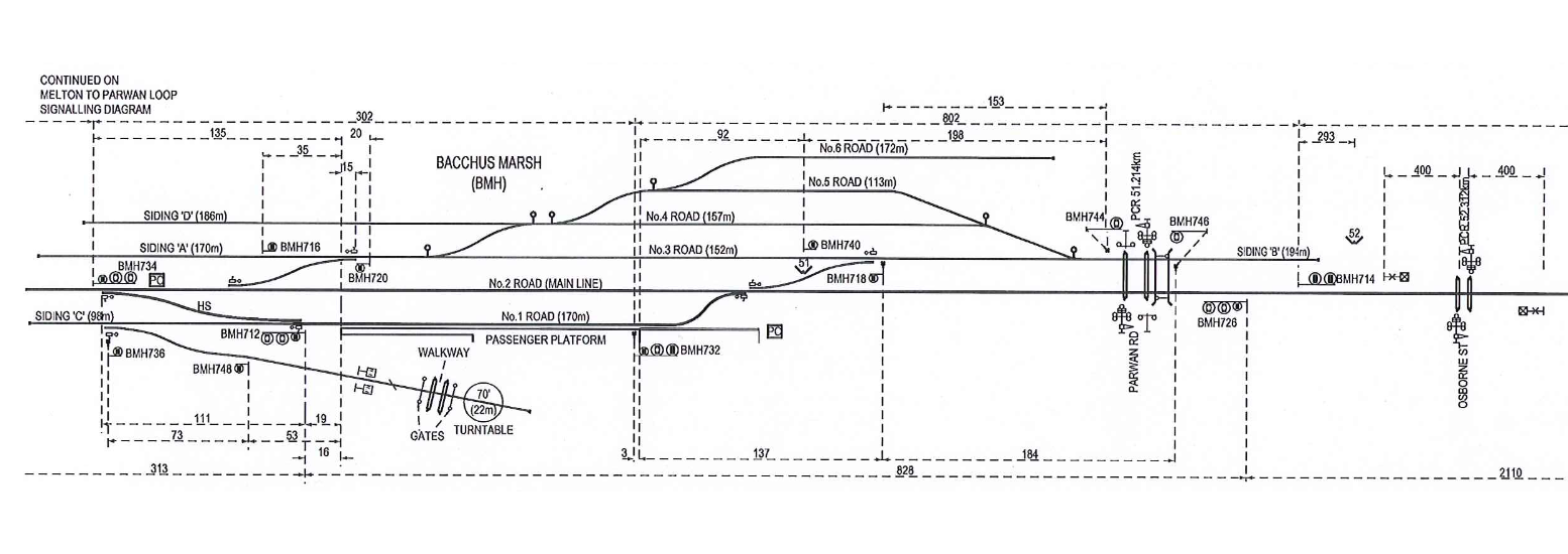
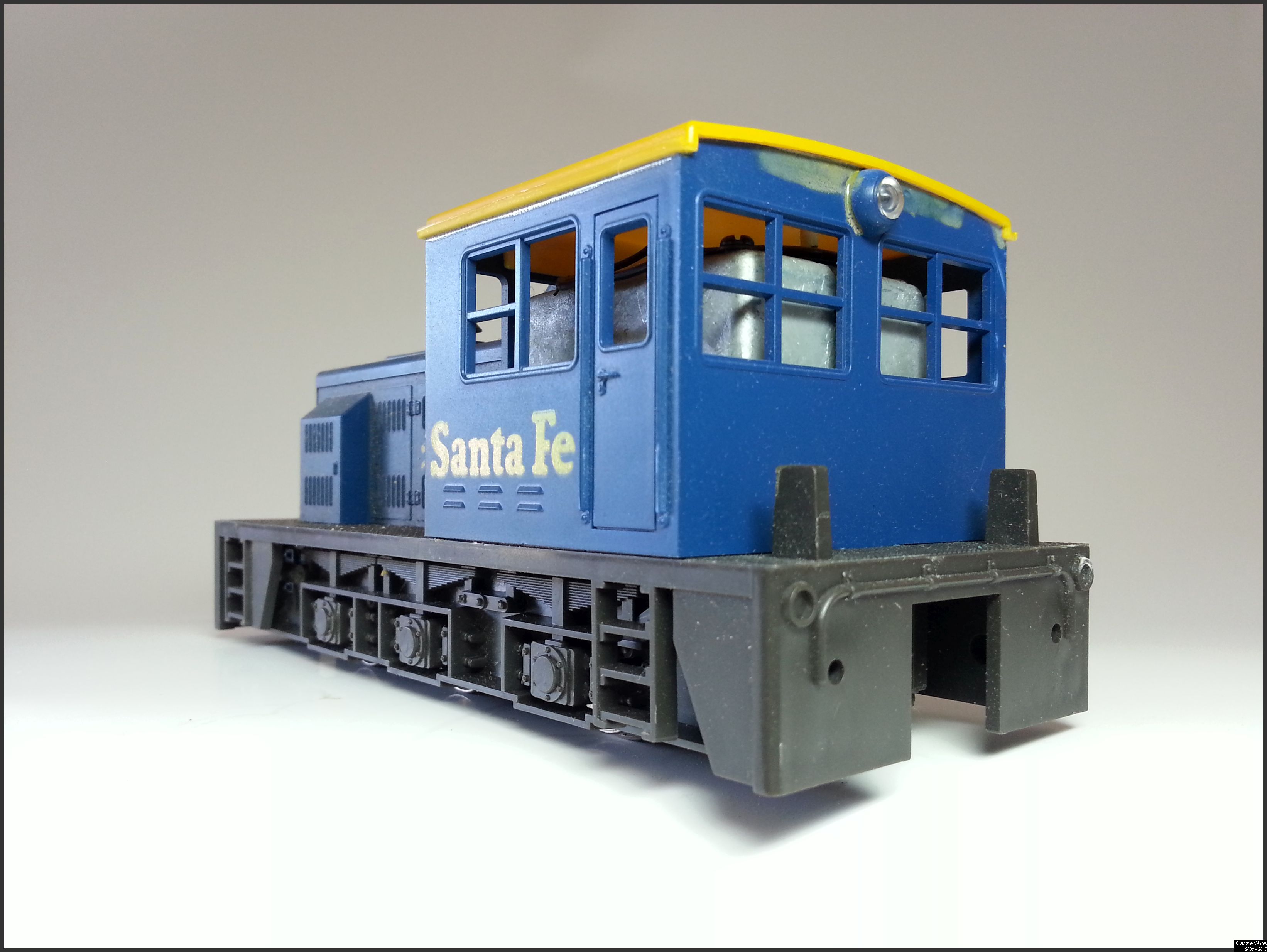
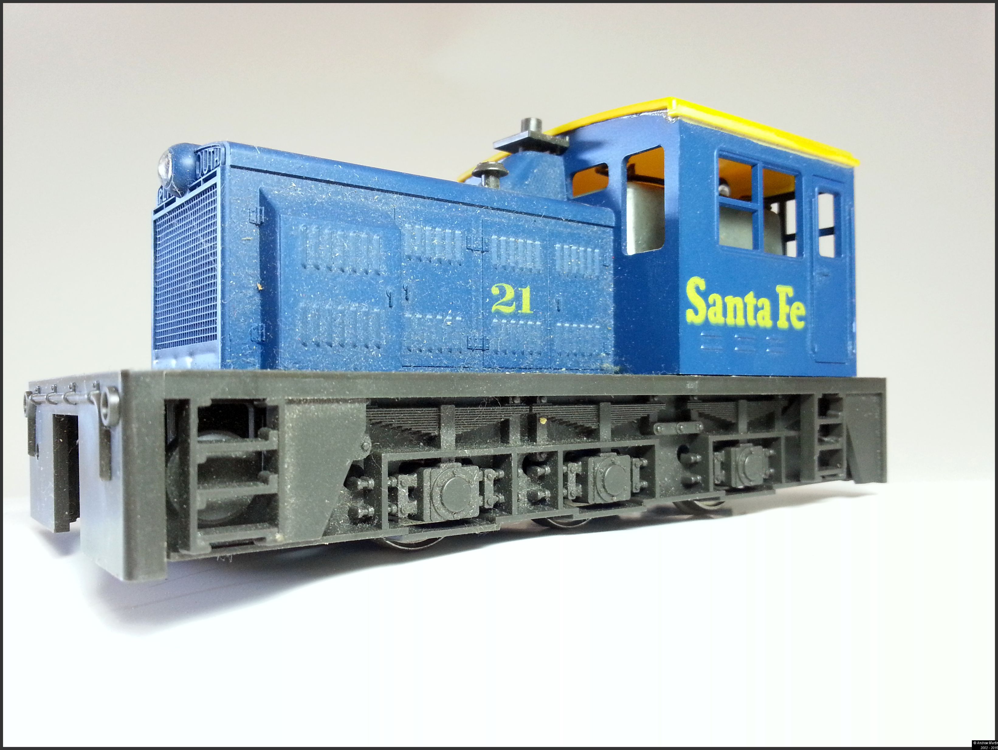
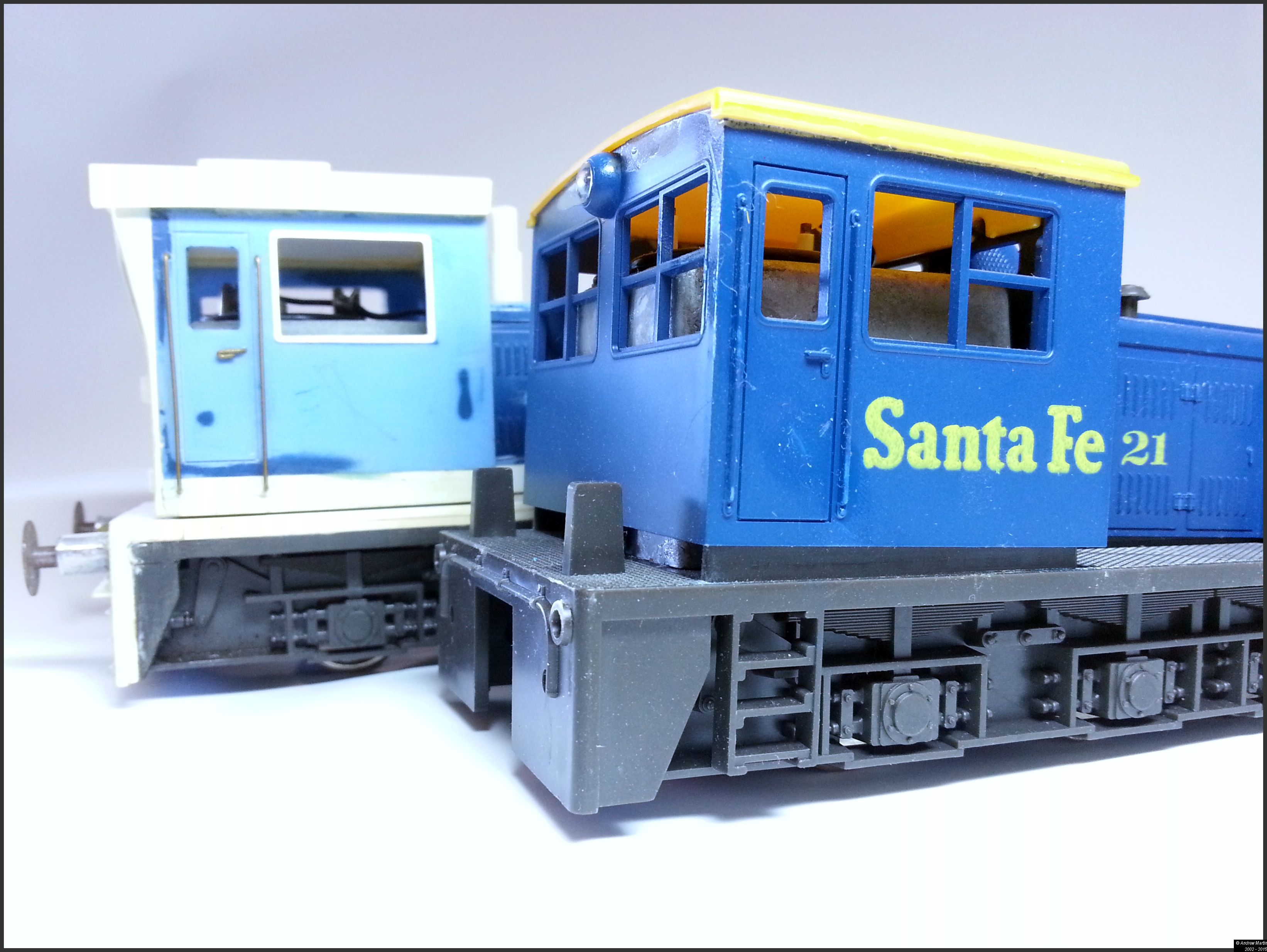
A long time ago, in a modelling landscape far, far away… there was a UK Model Trains magazine (I cannot remember the issue) that described the conversion of the Atlas O scale Plymouth switcher; the aim being to turn it into an industrial UK shunter.
If my memory serves me well it would have been about 1982 or there about. In short order I found myself owning four of these locomotives, and set about modelling the shunter as I’d seen it a couple of years previously. Having said all of this the title of this article now becomes important because I am about to finish the project that I started sometime back in the early to mid 1980s, in the mid 2010s. Yep – that’s 30 years.
That ‘Model Trains’ magazine article suggested either:
Keeping the cab height the same as it was on the original model and raising the buffer beam height to allow for buffers etc. or
Raising the entire cab by about a scale foot and raising the height of the footplate at the same time to allow for buffers to be mounted on the end of the frame.
I chose the second option as I wanted a snappy looking locomotive and not something half thought out that I’d never be happy with. So with magazine, (I have the copy somewhere and I’ll update the article details when I have them) plasticard, liquid glue, files and a sense of adventure I started working on the model.
I left the length of the loco as it was, and raised the body height with a conveniently wide piece of plasticard stock to get the height visually right. In reality that was the easy part as you’re just adding that to the bottom of the body.
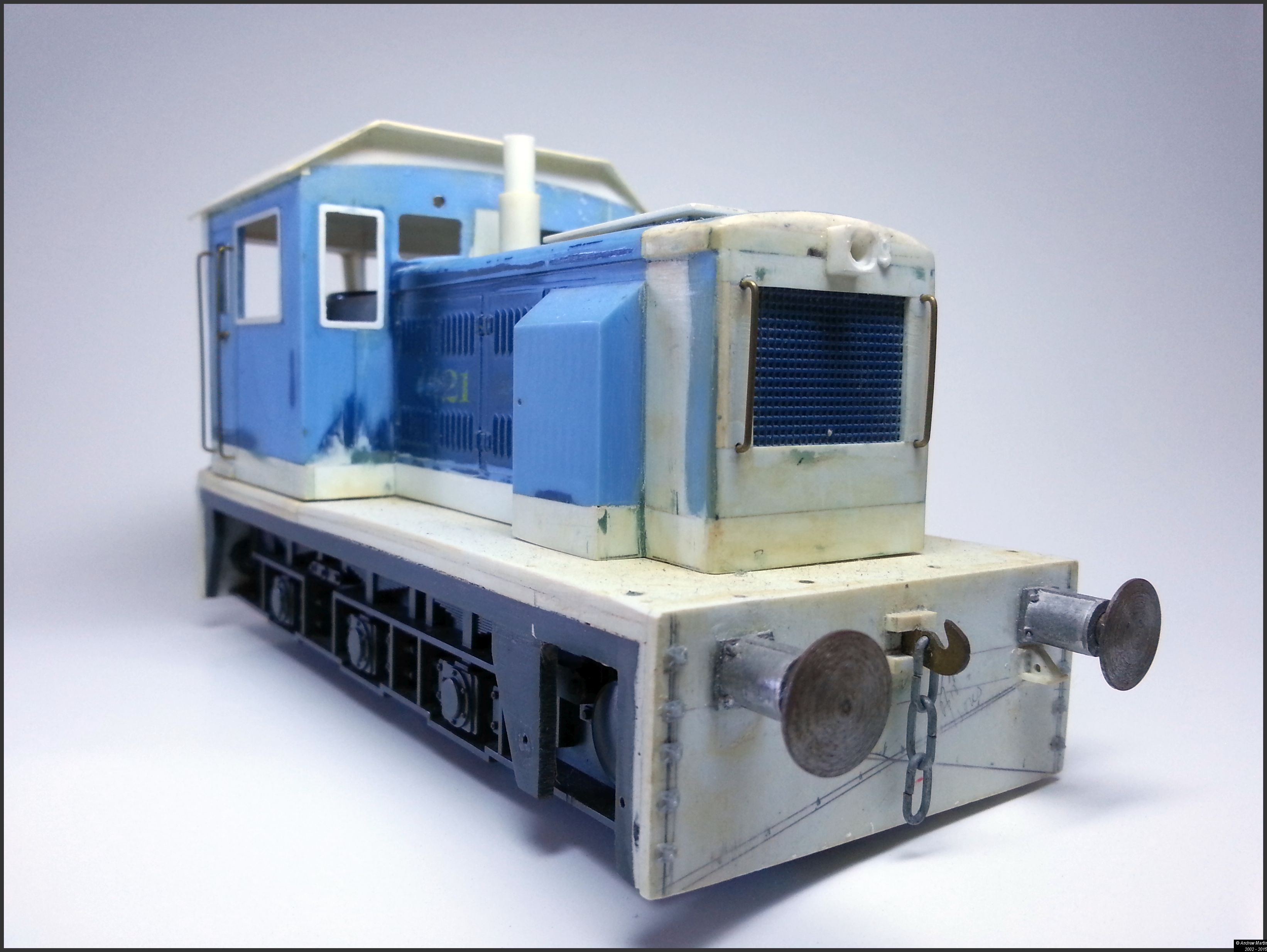
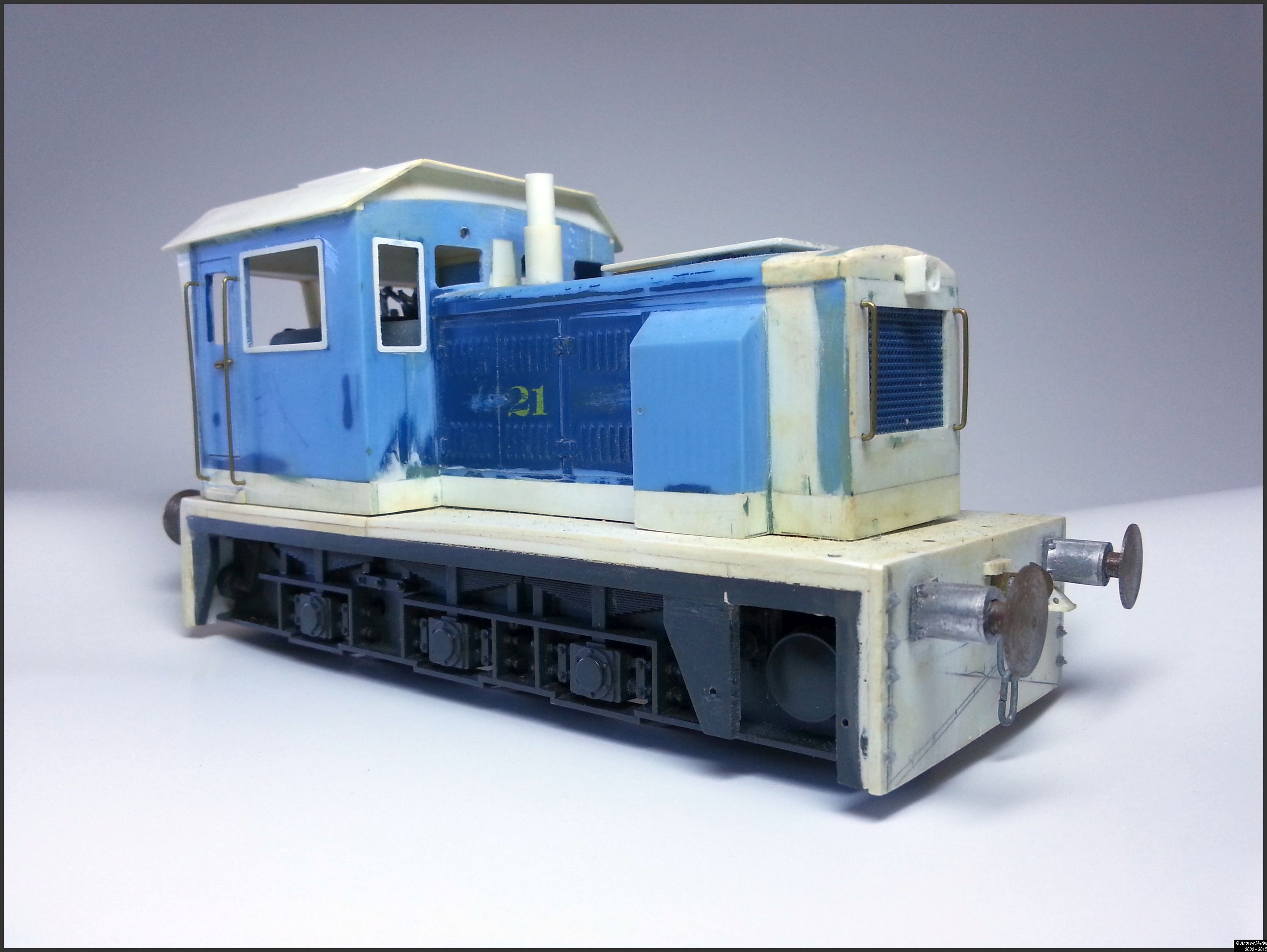
All images are Copyright Andrew Martin 2015 unless otherwise noted
In the four photos of the unmodified model note the squat nature of the body. The last photo shows the difference in height between the modified and original loco that the two 40 thou shims of plasticard give. It should be noted that the loco models that I have come with a textured surface on the footplate simulating a safety tread pattern. This was sanded down and removed prior to installing the higher floor.
Next I cleaned up the four pane windows and made them single pane. Finally I sanded down and covered over the buffing faces on the loco ends in preparation for the 3 link couplings and buffers. The only problem was that having put all of that work into the loco – it did not look right to me. It looked like a higher roofed American loco and not something that would have been made in or for an English railway, especially a Quarry railway which I’d always wanted to model (and still do). So it was back to the drawing board.
The second coming…
Unfortunately I only have photos from the second rebuild that I started in 1996 or there about and none from that first effort as it was back in the early 1980s and I don’t remember owning a camera at the time (being a poor electronics apprentice).
Before I begin any modelling project (I over think them to be honest) I do a lot of work on how the final model will look; This locomotive was no different. First was a working sketch that I scanned recently and cleaned up below. (Yes I store all my sketches of train models.)
Figure 1: Concept Drawing – Copyright Andrew Martin 2015
There are some differences between the concept sketch and the final model that I’ll be completing in the next week or two – overall I’ve come pretty close to what I wanted. I’ve not bothered with the end rails and chain nor the MU stand. As the quarry locomotives were generally run individually and not in MU service in the UK from what I can gather. Additionally I took about 10 mm off the rear end of the unit since I did not want the air tank or a balcony on that end with the new look.
The changes
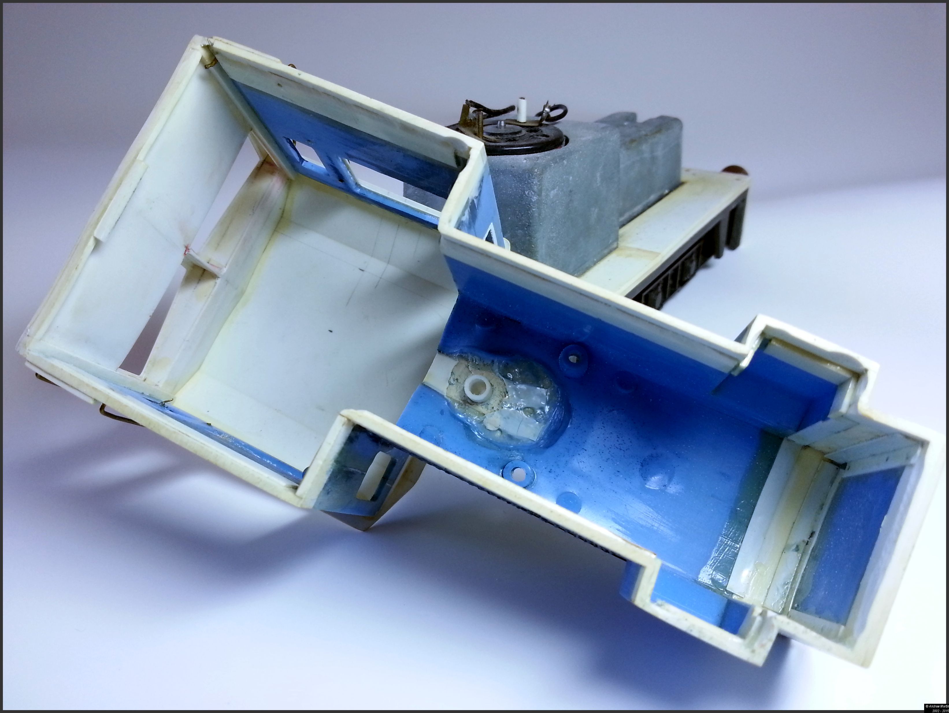
Photo 1: The extent of the surgery
If it’s blue, it’s not new. The bubbly mess of plastic in the cab end of the hood is what happens when you try and speed up curing of putty with an incandescent bulb. The stove pipe chimney was the result of that and not planned. However, I did add 5mm in the front of the hood to extend the hood forward and rebuilt the front top are of the hood too as the bulky light on the original just irked me too much to live with. The entire cab roof, and rear wall was sawn out, and a plasticard cab end and roof was put in its place. This sounds fairly straightforward, until you see the amount of work that actually went into designing and building the new cab end.
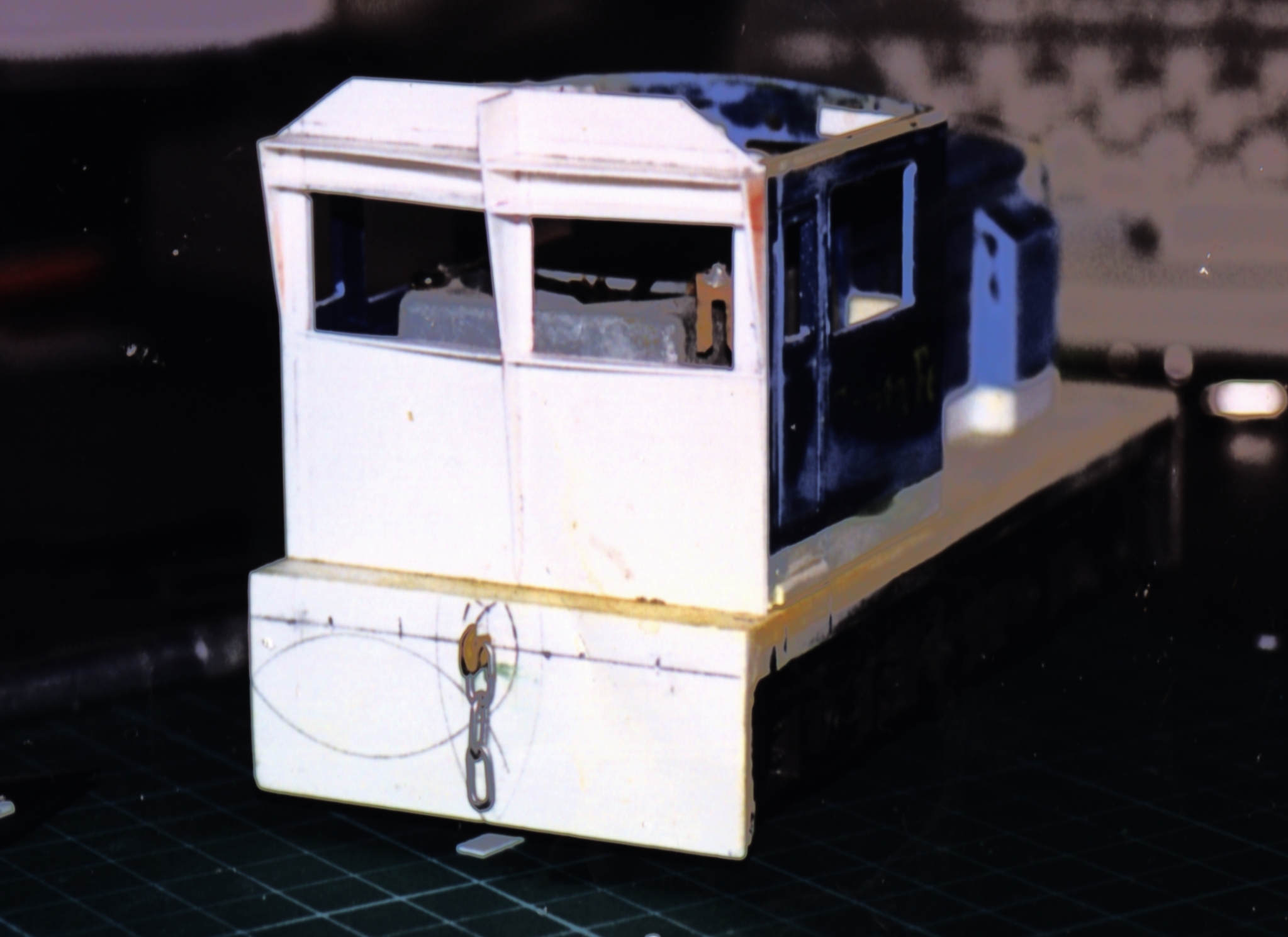
Photo 2: Cab end plate, and ribbing waiting for the skin to go on
Photo 2 above shows the planning and work that went into the design of the new cab. When the skin (10 thou plasticard) went on it was measured and cut in one piece to ensure that there would be no visible seams on the face of the loco. This went off without a hitch and I learned a lot out of that exercise that has helped me in my model building since. Photo 3 below shows what the cab looks like after the skin has been cut and glued in place.
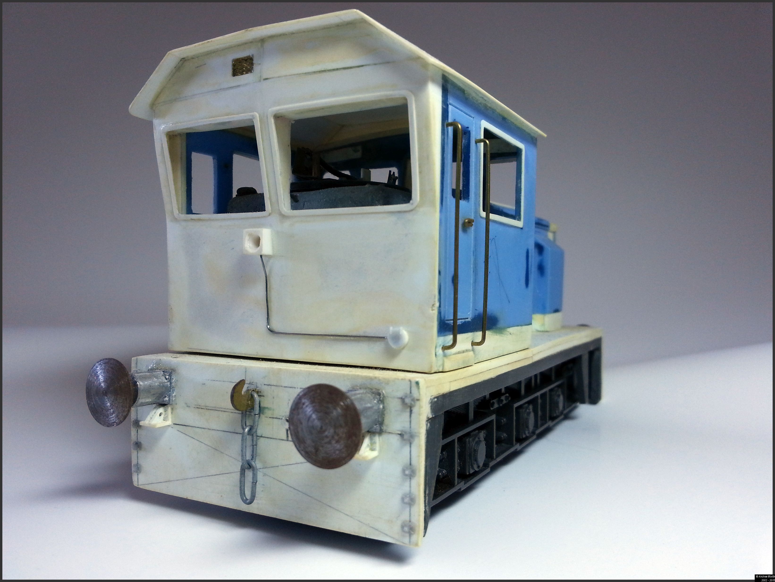
Photo 3: The new cab end completed
Also in Photo 3 above you’ll note the
Oleo buffers (from House of O Gauge in the UK – now gone I believe). These are working buffers and work as well as they look.
The electrical conduit to the light is fine solder Super-Glued in place. The light is a square styrene section with a circular section cut into the square frame and then drilled out to accept an LED. This will go back into the cab and into the DCC board. I had thought about having a duel sealed beam set, but I liked the look of this better.
To remove the need for a rear facing horn, I cut a small slot into the top left of the cab for the horn. I’ve yet to place a horn placed on the front of the loco.
The three link couplings are also working with draw gear behind them on the front and the back. Finally the electrical junction box is a 1:48th MU cover glued on to the face.
Finally the window frames are all 20 thou and allow a 0.5mm overhang into the window space. I am hoping to get some microscope slide covers cut and put in place in all of the windows. Should that prove too bothersome I will cut out some Monitor protector plastic that I’ve saved from work and use that in its place. It will be secured in either case by Revel clear cement.
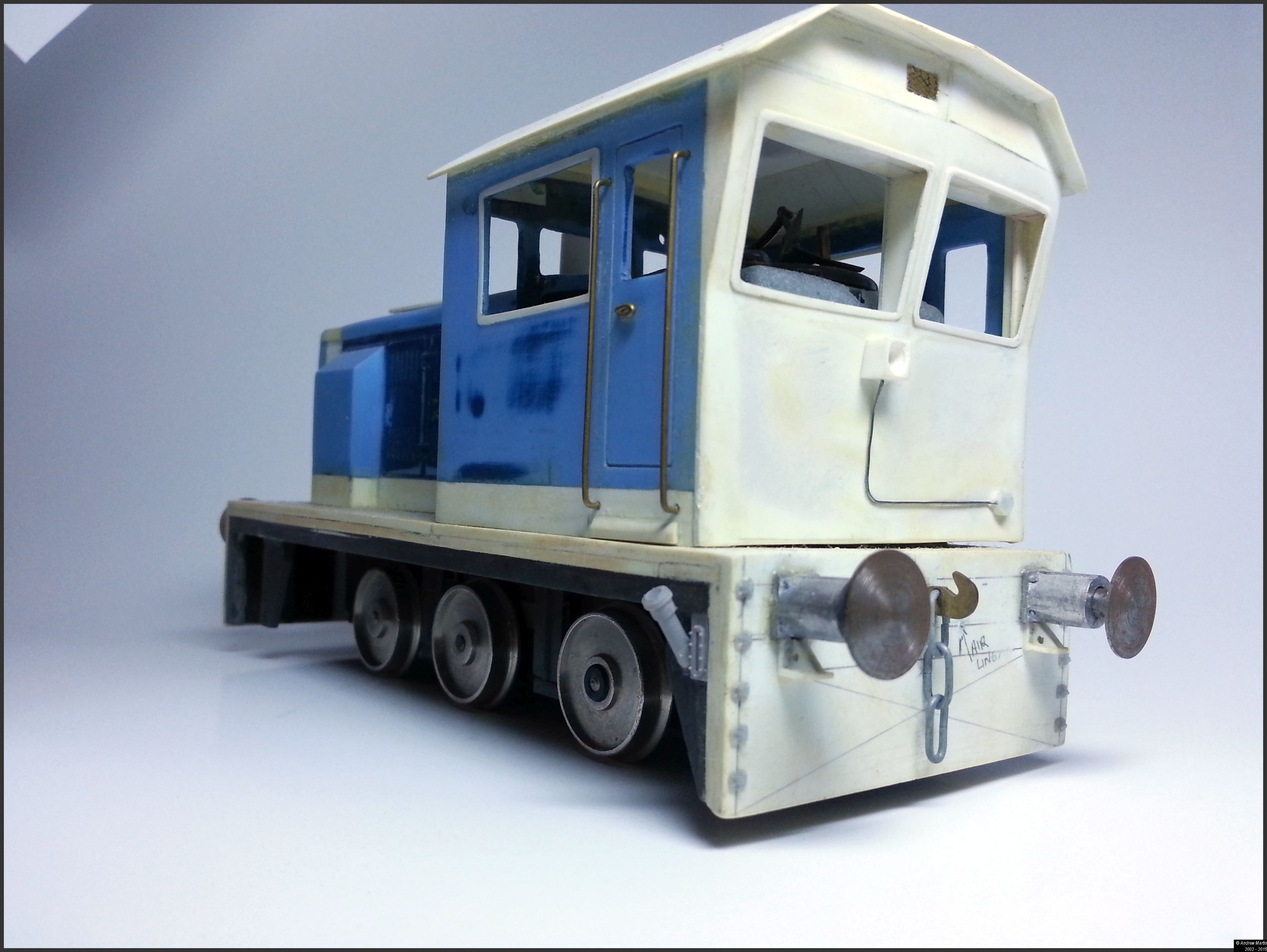
Photo 4: The front of the loco_
It’s getting late, so I’ll just add a couple more photos. If you have questions let me know in the comments and I’ll answer them for you.
Photo 5: A 3/4 view of the front of the loco
I’m not sure if I am going to leave the running gear showing like this or turn it into a tram loco. But the tram idea has me in its grip at the moment.
Photo 6: Rear left 3/4 view showing the fuel filler and tank gauge
The fuel filler and gauge are from a 1:48 scale add on kit I’m using on my GP38-2 rebuilds.
I wanted to show my working (as my Math teacher always encouraged me to do) on the layout design as it evolves to meet my needs. I was not happy with the way the original design performed when I looked at the yard throat design. There was an ‘irksome’ separation between the mainline and the branchline running into the future Industrial park extension. Image 1 below, shows my attempt to fix that issue; a simplified version of the first track layout.
Image 1: Take 2 on the layout design
The throat area is the set of switches around the Interchange track and the branch out to the rest of the industrial park. In mock operating sessions the biggest issue I had on the fist design was the lead out to the rest of the industrial park had crept down quite a way onto the upright of the L shaped boards. Keep in mind here that the other boards are not yet attached to the three boards in the image.
Additionally, I wanted to have a better yard throat, that was easier to switch through and took up less space. After due reflection, the layout just didn’t look right for a small, smart industrial line with the smarts to build their own industrial park out of a couple of abandoned branch lines. Thus we arrive at version 3.
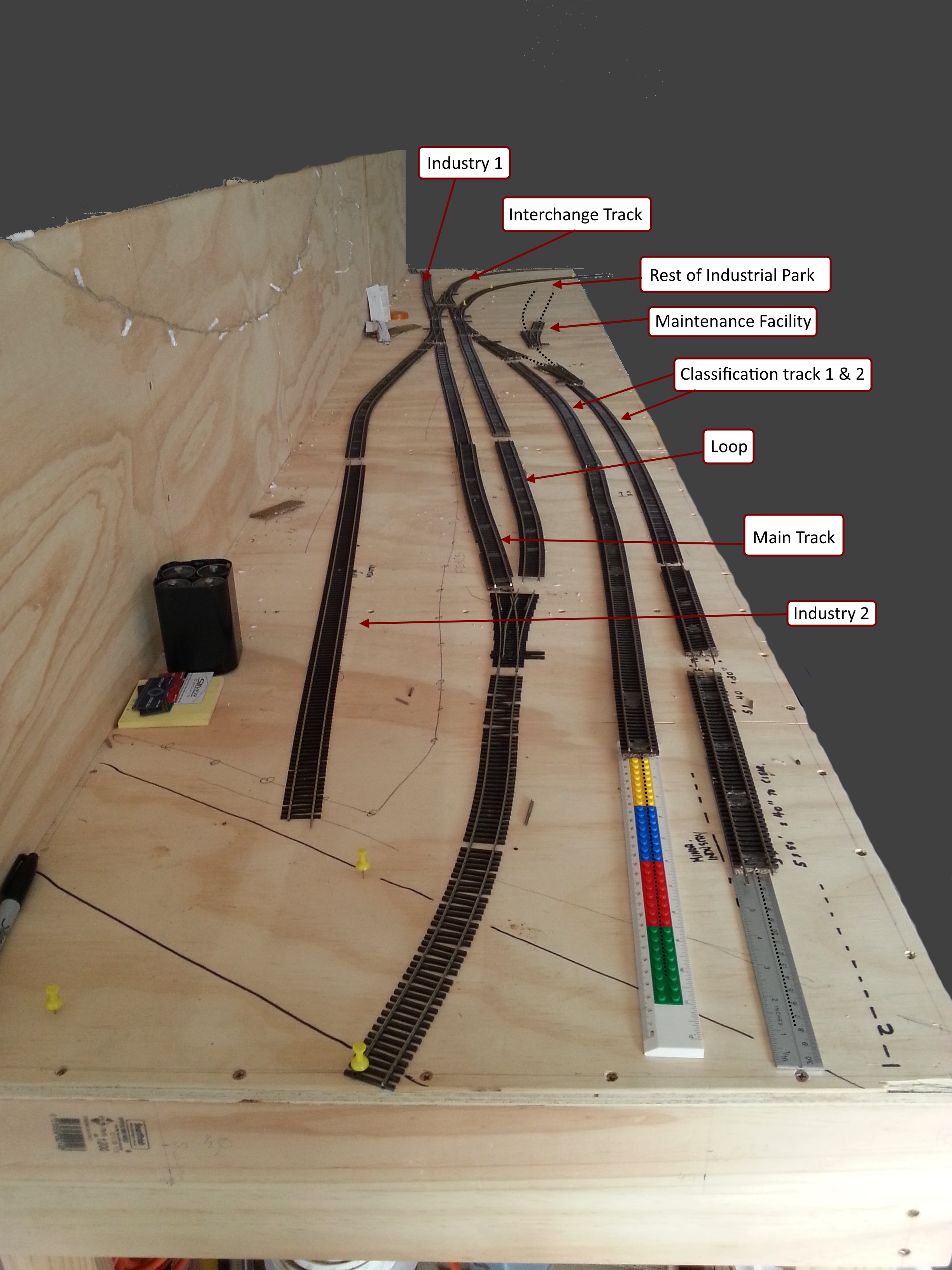
Image 2: Take 3 of the layout design
First there’s a better use of space,and visual appeal (to me anyway) with the long classification track #1, and the maintenance lead / class track # 2 being at the front end of the board.
All of it coming direct off the old main (now the interchange track). It simply feels better, and right in a way that the previous versions did not. I’ve run a quick thought exercise ops session on the new layout, and it also makes it easier to do business on the new layout. I’ll post the results of that a few days in the future once I have some other modelling work that I have to complete done.
On reflection I will be moving the switch (currently a Wye that will be replaced with a left #5) further back toward the camera to extend the run-around on both the main and the loop. This will stop just short of the road overpass and ensure that a loco can pull clear of the switch to allow the run-around move to take place. Additionally it will allow the
That’s it for me at the moment. Talk to you all later. If you have any questions let me know.
So much for catching up! I had promised to catch up on my posts after a long week of the flu; Sun Tzu was right – no plan survives first contact with an adversary (or a past time).
Site 1: BobbyPitts44 build of a flexiflow car
Over on the FreeRails forum (Link Here) there’s a brief discussion on the work done to take what is essentially a 1960s era toy freight car and turn it into a scratchbuilding masterpiece.
While the forum does not have a lot of information on the build, luckily his Flickr site does. Everything is back – to – front, but there is some really amazing work there to be viewed.
Lance Mindheim is a force in the design of operational layouts. Today’s site seeing tour takes us to an article on his views and to his new website (built on WordPress no less).
Site 1: Railroad Model Craftsmen
In this article (offsite link) Lance talks about the play value in our layouts, and how without the play value, the layout will in the long run fail to please.
Site 2: Lance Mindheim’s new site
Lance has moved his site (offsite link) across to a new platform that finally allows searching. He’ll be updating and moving older content across to the new site over time. But for the moment the link I’ve provided takes you straight to the blog. This is where most of the content is right now.
It’s all operations Saturday, thanks to Martin Hogg, the owner and operator of Brett.
Site 1: Brett – a full operating session video
Martin Hogg’s released a new video (Brett’s been featured recently on the blog).
This time you get to see a full operating session from start to finish.
This video shows just how much enjoyment you can derive from switching on a relatively small layout with a reasonably simple track plan.
I’m guessing the operating session lasted around 25 – 30 minutes from start to finish. As soon as I get some feedback from Martin I’ll update this post and let you know for sure.
Good work that man! On you Martin.
Update 1:
I talked with Martin Hogg today and he confirmed that the operating session takes about 25 minutes (although he says its heard to be sure as he was busy phaffing around with the camera to be sure). He’ll be running another session to confirm that but I’m pretty sure that it’ll be right around the 25 minute mark, depending on the work to be done.
I’ve known Chris Gilbert for many years thanks to the Internet, specifically RMWeb. Chris has always managed to be a great mentor on things model railroad, even if he was not aware of his mentorship. He’s been successful in building, exhibiting and publishing a range of model small exhibition layouts over the last several years. What gets me is how quickly he puts these model marvels together.
Florida Springs (V 2.0) – An HO Scale exhibition layout
Chris in his own style said that he started the layout on Tuesday the 10th of February with a trip to his local hardware store.
Within five days he was at this stage:
As if that was not enough to make me feel like I need to pick up my game, his detailing is exquisite. If you take a link at post number 5 (link here) you’ll see what I mean.
Every time I see what Chris can do in so short a time, I am simply bowled over. He thinks about something and then he gets it done. It’s something that I am going to aim for in my modelling this year.
Before I can get there though I have to complete some other modelling projects to finish for my local model club show in April (you can read more about that on the Modellers of Ballarat blog (link here).
I’ve listed other sites in the resources section below. Enjoy having a look at Chris’ layouts. They really are magnificent works of art.
Resources
· You can find out more about the O scale Fort Smith Railroad layout (External Link) here.
· You can visit Chris’ YouTube channel (link here) – and watch his videos of Haston and North Haston – great stuff.