Category Archives: Layouts

All layout subjects

The Galveston Island Railroad Museum

In September of 2000 the family and I took a visit down to Galveston, on the Texas Gulf Coast. Among the great things to view was the Galveston Island Railroad Museum. I’ve scanned some photos I’d taken on the visit of Southern Pacific NW-2E No. 1303.NW2_SP-1303-0

She was built in June 1949 by G.M.- EMD as # 1925 and when rebuilt in April 1971 became #1303.

NW2_SP-1303-03

She was donated to the Museum in December 1984 and was operable when I visited.

I hope that you enjoy the images. You can find out some more about the museum by visiting their website: www.galvestonrrmuseum.com/

Progress Rail in Waycross Georgia –

As someone with little space, and limited funds to put toward layouts, I am always looking to find that next great small layout idea. With my role at work coming to an end unexpectedly this week, a small lower cost layout is even more important than ever. While spending some time getting to grips with redundancy I was idly looking at image sites when I came across the Progress Rail facility in Waycross Georgia.

It is a great little facility that has storage for the locomotives coming in to be worked on or scrapped, and then a couple of simple buildings for work to be done. The layout of the track is very simple too. I’ll post updates on this post with additional images once I’ve completed the work on the images.

For now you can look at the following links here:

Videos:

Images:

I’ll post a plan and some other images I’ve found here soon.

Andrew

The new layout boards are complete!

Originally Posted on the Old HVL blog March 24, 2013

OK, so a little about the design and build of the layout boards.
In general all wood is fine quality pine dressed all round (DAR). The board top is 12 mm ply (1/2 inch), while the sky board is 6mm (1/4″) ply. THe legs are “L” girders using 1×2 and 1×3 DAR pine glued and screwed on the along their length. At the base of the leg is a glue bock of 2×1 DAR pine which is used to locate a T nut, with a 5/16″ bolt as a leveller. The nut for the 5/16th bolt mounts on the top of the glue block locking the bolt in place once you’ve levelled the board. I’ll be building a better foot arrangement at some point in the future that is easier on the floor, most likely a wooden ball with a 5/16″ nut through the centre of the wooden ball.

All of the side and end rails are 3 x 1 DAR pine and these have not been glued, but have been Kreg pocket screwed together. The ply was then glued and screwed to the box. Nice, tight and very rigid. There is one rail across the board in the centre  of 2×1″ DAR pine, this has also been Kreg pocket screwed to the sides and the top was glued and screwed tothis also. The skyboard is glued and screwed to 1×2 pine DAR which acts as a stiffener and mounting point on the back of the main board. Mounting to the rear of the main boards is achieved using Kreg pocket screws.

The legs are mounted to the main board using 3 screws on each side to the sides. The top horizontal board bears the weight of the main board above; while the bottom horizontal board acts as a bearing face between boards and allows the boards to lock together using a wooden clamps from offcut of the hozontal boards and 1 x 2 DAR pine. Think an inverted U locking the two legs together. Nice, tight, simple and about 3 months in the planning.

Overall what are my impressions? Very happy to be over the hump of the work. The boards are light and strong. I can lift them fork lift style on my own without hurting myself and as I have a 50 year old back; this is a good thing. Thanks to my wife (Janette) for suggesting the mounting height for the sky boards. At 400mm above the plane of the board they are high enough to be at or just below my eye height, and with the 2×1 stiffeners behind allow easy mounting of lights that will hang out over the board for better simulation of daylight.

I’ve a few sketches and such to put on the gallery site later in the week. This should give you an idea of how the parts look. More photos will be coming before I paint everything later this month or during April, depending on the weather. Well a great day in all, now some remedial work on the old boards to bring them up to spec and height, and then my work is done.

A Texas Inglenook prototype – The ADM Mill facility New Braunfels

Occasionally for the small layout builder, a prototype comes along that you simply cannot forget. The ADM Mill located in New Braunfels, TX is a perfect example. A simple Inglenook switching location that could be built as a standalone, or incorporated into an existing layout as a peninsula. The site when I took the photos in 2004-5 was used mainly as a hard wheat facility. In the past, though it had been used for milling multiple grains as well as corn.

This photo shows the whole of the north side of the facility. Of note is the circular storage silo in the foreground which has 7 separate silos within it to allow storage of different types and kinds of grains depending on the season. The other photos in the set show different sides of the facility buildings mainly from the grade crossing on E Mill St, or further up the road in the case of the Southernmost photos.

Essentially the site lies East-West; the road crossing runs North-South. The main Mill lies on the Northside of the tracks and is the oldest part of the building; the newer storage silos on the south side look to be built during the 1970s. The main office building is on the East side of the mill, across San Antonio Street, on the East end of the Mill. Once you see the overview you’ll get a better lie of the land.

All in all, this is a nice simple Inglenook and can provide the operator with plenty of work in a small space, with nothing more than a TrackMobile for motive power. The staging can be cassette, plugin or hidden depending on whether you are using this stand-alone. If you love covered hoppers though, this layout will appeal.

ADDITIONAL

You can view the entire album of images at the following link: –>Click Here<–

More on the new layout

Originally posted on the old DasBlog – Thursday, March 28, 2013

While I am not working on the layout of a weeknight, doesn’t mean that I am not thinking on the layout.

My son Ewan (who is 8) got me to thinking about a new layout after a Sunday morning spent switching on a plank I have setup for testing car and coupler heights and and so on. He enjoyed it so much, big smile – the works, that he asked me to build something bigger because he liked driving the loco up to the cars and switching and coupling/uncoupling the cars so much.

He is a mad gamer, and is asking me to help him learn to code so that he can write his own games. So I figured why not make sure that he could “role play” with the locomotives and cars. I have spent quite some time getting the physics of the locomotives right in the decoders and this has formed the basis of my thoughts for the new layout.

What I have currently

I have the following DCC loco’s:

  • 2 x Bachmann 70 Tonners (cause I love them – one in Red and the other in Green – and yes they are noisy enough without sound – working on a fix for this in the future)
  • 1 x BLI Trackmobile (which moves like honey in summer it is so smooth and oh-so-nice to switch with…)

I have the following DCC & sound equipped locos:

  • 1 x BLI EMD SW7 (in UP colours – my Wife’s favourite scheme)
  • 1 x Proto 2000 GP20 (also in UP colours)

What all of this means to the emerging layout design is this:

  • Long runs where ever possible: This allows the physics that I have programmed into the locomotive’s decoders to come into play. For sound equipped locos I have made sure that the SW7 takes a shorter time to load up before pulling away. This simulates the locomotive gearing, while the GP20 takes longer to load up before moving off for the same reason. Once a loco is moving, having watched a lot of videos on you tube, the power is usually cut and the loco coasts. I can now do the same thing with the Deceleration set reasonably high to ensure that the loco will slow if going up a grade, and maintain or speed up slightly when going down grade. When I need to stop I give a brake application (F7 on my MRC Prodigy Advanced 2 system) whence I get brake squeal, and the locomotive and train stop where needed.
  • Proto weighted cars where possible: I use Kadee trucks This ensures that the cars track much better than NMRA weighting standards. I use Kadee trucks under all stock and it they run much better when they are weighted properly to compress the main springs. I use a cubed root formula spreadsheet to track each car type and the weight they should be carrying. One nice side effect is that the clickety-clack as trucks go over rail joints sound much better in my opinion.

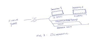
One location that is getting serious design time right now is a Miami Transload Facility. My version would only have three tracks in the Transload facility, the centre one being an overflow (99 off spot according to the SP) track that would also increase the switching.

In the background I am still thinking of adding the bakery that Lance Mindheim wrote about. This effective uses one switch for two long sidings. This would allow the two locations to be switched separately, but different operators that are still within arms reach, and yet still stay true to the area they are modelled on.

During my original planning I had though of extending the design from the 12 foot board through to the 8 foot return board, and using a rotating sector plate (rotates completely through 360 degrees) on the final four foot board with an overhang to provide staging.

Still thinking this over as well as the Boxcar Haven design. More thinking at the moment, will yield a better design in the end. Thanks for following the internal monologue; any comments are always welcome.

What does operations mean for a Small or Micro layout?

Originally posted on the old HVL DasBlog –  Wednesday, May 15, 2013

Introduction
For the small layout builder/owner/operator their exist challenges that modellers with larger layouts do not face. For example; if you have a 20 foot long layout with additional staging your trains actually do go somewhere, even if it is only 20 feet. But they do go somewhere and switching takes place in more than one location. On a Small or Micro layout the same is not true. Often you’ll be able to see everything all the time. In order to give the sense of operations I came up with a set of “rules” for the game that provided me with a starting point, an end point, and the means to know where I was in the game of “MR Operations”.
The Game
MR Operations is no different to Monopoly, or any other board game. You have pieces, that move in a certain way, according to set rules on a pre-configured gameboard. There is a known starting point and an end point of the game, although this can be changed by mutual agreement of the players.These are my “rules” so far as Small/Micro operations go:

  1. Trains must come from somewhere (they enter the stage)
  2. Trains should do one or more of the following whilst on the modelled portion of the layout (on stage)
    • Change Direction,
    • Change Consist,
    • Do work appropriate to the nature of the train.
  3. Trains must go somewhere when finished the actions outlined in point 2 above (exit the stage)

While formulating this simple set of three rules I took into account all types of layout designs. Thus the rules allow for:

  1. Double ended Small/Micro layouts
    • with fiddle yard to fiddle yard via a station/named location
  2. Single ended Small/Micro layouts
    • with a fiddle yard at one end and a terminus on the modelled portion of the layout
  3. Freight only operation
  4. Passenger only operation,
  5. Loco only operation or,
  6. A combination of any and all the above.

I developed the idea of a SuperNook before I had setout the rules above. However the reasons behind it were clear in my head. I wanted a freight based layout that provided all of the functions that you got with a UK based end of branch layout, that could be applied to almost any style of railroading, anywhere.

Image 1 is an example Supernook.


Image 1

The Supernook in Image 1 above has five distinct zones:

  1. A – is the switching lead/branch/main line – depending on the layout style
  2. B – an industry lead/storage siding
  3. C – an industry lead/storage siding
  4. D – is a passing siding/loop
  5. E – is the short switching lead to allow a run around to occur and/or the entrance or exit from the modelled portion to another fiddle yard

The SuperNook provides the Small/Micro layout operator with a purposeful and practical method of play, that keeps interest for the longer term. The rules do not take away from Car Cards, TT&TO, DTC or any other operating system, they do however focus the mind on what you want to achieve from a small layout and give you the means to map out the path to get you there.

Summary

Small layouts allow for greater detail but can suffer from limitations to operation. By using the rules I’ve confined myself to above you’ll achieve more satisfaction from your creations, have greater enjoyment in the longer term, through a better more flexible design that allows for better game play.

Regards
Andrew

HO Scale Supernook

Posted originally on the old HVL DasBlog – Friday, June 07, 2013

Operations and Display Running

Apart from building my new (largish) layout at home, I have promised to provide a small layout for a show next April. The industries can depend on what type of cars you want to run, but the classic inglenook approach still applies of a 5:3:3 Inglenook within the Supernook.

The Supernook is my modification of Alan Wrights classic Inglenook. The Supernook though provides the means to turn a train, that is reverse its direction through the use of a loop to allow the locomotive to swap ends of the train.

The premise being that the train:

  • Enters the stage, in this case from stage left (staging),
  • Breaks down its incoming train,
  • Switches the industries
  • Makes up its outgoing train, and
  • Then Exits the stage to stage left (staging)

Exhibition operation

Apart from talking to people who are interested in modelling at our exhibitions, the most fun I’ve had is to make things work, or show others how things work. To that end I want to present a layout that would keep my interest, and the interest of the viewer for perhaps 5 minutes while they’re wandering around the show.

If I get lucky and I have someone who wants to have a go, and gets into the spirit of Operations then all the better.

The Nitty Gritty
Here is how I would see an operating session go on the new layout:

  1.  Our train arrives from off-stage, and parks itself on the branch main,
  2.  The crew:
    • Sets handbrakes on the cars,
    • dumps the train air,
    • cuts off the caboose or guards van from the rear of the train,
    • cuts off the engine,
    • runs around the train using the Loop track,
    • couples up to the caboose, before pushing it forward to the tail track on the branch main to clear the loop for switching.
  3. The conductor or guard checks the bill box at the entry to the industry track
    • The paperwork here tells the crew which cars are to go where along the industry track
  4. The crew:
    • Climb aboard the loco, and under direction of the conductor/guard:
    • pull the outbound cars from the industry track to the loop,
    • move off-spot cars and the incoming cars from the branch main to the industry spots at the end of the track, continuing to back-fill the industry track until they have completed the switching instructions left for them by the customer.
    • Any cars the crew could not place at the industries are pushed into the storage track.
  5. The crew with all switching moves completed begin the task of reassembling their train and readying it for departure:
    • First all of the outbound cars are marshalled together, and if so required may be blocked for delivery to other yards and industries,
    • Remember that as cars are put together into a rake, brakes must be unlocked, airlines connected and air pumped to operating pressures. All of this takes time, so slow down and account for that time.
    • With the train now almost formed the caboose, previously set out on the tail track, is connected to. The air pumped up, and a set and release performed to ensure that all brakes on the train are working.
  6. Finally with a train ready to depart the whole consist leaves the modelled portion of the line, stage left, for the fiddle yard.

This completes the operating session.

Additions

You can increase the level of operation on the layout by having in-plant switching taking place in addition to the interchange operation by the delivering railroad. In-plant switching would involve the local switcher, either leased, in-plant or track-mobile moving the cars from the doors/loading docks/UT Auger as they are unloaded and placed out on the storage road, pending the interchange move with the delivering carrier. The aim would be to use the loop and branch as needed, but to have them clear by the time the interchange carrier is ready to arrive. Say give it ten minutes to ensure that you have everything cleared out of the way to allow the interchange loco to run-around the train.

Enjoy
Andrew