After I reblogged Rails West’s San Fernando Valley Branch post on December 7th I took a look around the web to see if there were other sites that had information on this very interesting branch line. Luckily I found one. I could not find a SPINS book in my stash of SP paperwork to cover the area however you could certainly find this information from many of the online dealers (found at the last link) today.
There’s a week’s worth of information here and I hope you enjoy reading through it all.
Bruce Petty’s website has some really fine information (including lots of photos) of the branch in the early 1908s that would of interest should you decide to model the branch or one just like it. It includes the names of the industries served and the car lengths of the spurs.
Another of Bruce’s pages this time with photographs of the freight stations along sections of the line. Nice if you wanted to model any of these buildings specifically.
Bruce has a model railroad covering a portion of the branch that was featured in the 2007 Great Model Railways (Kalmbach Publications). Take a good look around and take a look at some of the links on the page for the modelling articles there. Really goo stuff.
A great site with a huge range of detail and links about the SPINS system and the TOPS system. And yes UK modellers that is the same system BR purchased from the SP in the 1960s.
Today is also marks my brother’s birthday – so Happy Birthday Scott. Hope that you get the message. More importantly I hope that you are reading the blog! But enough of me and onto the site seeing!
Site 1: One turnout layout variation
I’ve mentioned Chris Mears’ site in the past. His current post provides some interesting thoughts on variations among other thoughts on the “One turnout layout” posited by Lance Mindheim in the May 2013 edition of the Model Railroad Hobbyist Magazine.
Read the article, and then read, and take part if you’re willing, in the discussion at the end of the post. It’s been thoughtful reading. Not saying that I agree with it all, but it has been thought provoking.
This is the small layouts section of the old HunterValleyLines.com/gallery website that is now offline as mentioned in my post yesterday. There are over 30 layout designs in this section.
This is the most interesting and fastest growing section of the website. The Ideas and scribbles section is the storehouse of all of the doodling and noodling that I’ve done over the years. There are narrow gauge loco designs, industry designs, layout ideas and designs but all are drawings only.
On June 02, 2015 I made mention in a post of a grain silo operation close to the CBD in Melbourne, Victoria that allows for interesting operation, and would keep a model railroader busy and interested for the length of a short operating session (around a half an hour).
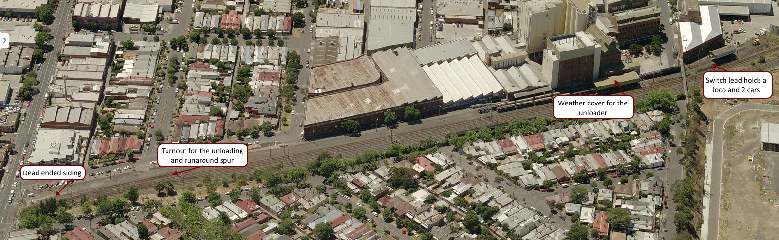
Image 1: G529 stabled in the dead-end siding at Kensington. The grain hoppers and the switch engine are down by the flour mill (courtesy of wongm’s rail gallery – LINK)
A little background
For those of you not in Australia let me give you a little background on the site from image 1 above. The photo above is from the grade (level) crossing at Kensington station. The station buildings are directly behind the photographer. G529 is sitting at the north end of the site on a dead-end siding used for second units or for red-carded (bad-ordered) cars.
The two lines under wire are the UP (left-hand line to Melbourne) and the DOWN (right-hand line from Melbourne) lines to the outer suburban terminus of Craigieburn, a fast growing suburb 26 Km to Melbourne’s north. Grain trains come north from Tottenham Yard and back into the sidings. When they leave they have to do a long looping route north, then west before returning to the yard once more. A fair bit of this is on the suburban Craigieburn passenger line. This situation occurred because of changes to rail lines for the Regional Rail Link that has taken freight lines out of service.
The single slip allows access into the site from the DOWN line. On the mill site there are two spurs with the left road running over the under track unloading auger; the right is a passing siding. The switching problem on this site is that the turnout at the end of the two roads only has enough room for two grain cars, and one locomotive at a time.
Image 2: An overview of the site (courtesy of Bing – LINK)
Operation
Generally the train has two locomotives. While a single locomotive can handle the work, and would be easier on the crews when switching, the extra power helps clear the path for the passenger services on the Craigieburn line. Melbourne’s rail network is greatly used by the it’s citizens and the infrastructure is congested requiring new signalling to allow greater train density. Anything that holds up one train has knock-on effects that can and do regularly impact on the rest of the network. So any freight movements using passenger routes tend to be over-powered.
Image 3: A track diagram showing the grain siding and signalling at Kensington (courtesy VicSIG)
1. Arrival
The shift begins with the loaded grain train arriving early on the north-bound suburban tracks. The train pulls into Kensington stations up platform road, before informing train control that they are ready to reverse into the facility. Train control (under CTC) unlocks the shunt signal 7, switch 8 and switch 9 to allow the movement and the train reverses into the site, putting the grain cars onto the ‘left-hand’ unloading road. On completion of the move the crew contacts train control once more and the switches and signals returned to normal.
2. Set up
The crew has to unload one of the locomotives. Without the room to run the power around at the switching end on the unloading road one loco is usually parked on the ‘B’ siding at the north end of the site. Image 2 below shows the problem on-site with the short headshunt (switching lead).
Image 4: The switching problem – the short headshunt (courtesy of wongm’s rail gallery – LINK)
3. Switching / Shunting
Prior to unloading beginning the mill staff remove the metal grate covers to allow grain to begin unloading into the under-track auger. With only one loco for shunting (switching) the operation is fairly straight-forward:
The first two cars unload at the under-track auger
When unloaded the train pulls forward to two car lengths to begin the unloading process again and handbrakes are applied
The loco cuts off the two empty cars, pulls them to the headshunt, before pushing back onto the passing siding
Handbrakes are applied on the two empty cars before the loco cuts off and moves back to the headshunt
The loco reverses onto the loaded cars, and the cycle repeats until all the cars are empty.
With all the cars emptied the mill workers cover the auger pit with the metal covers. The loco eases off the unloaded cars, runs into the headshunt, and backs through the unloading road back to siding B. Here it picks up the previously stabled locomotive and once MU’d they back onto the empty cars; with the air pumped and they wait for train control to authorise their return to the running lines.
Modelling
Operation of this layout design element offers a lot of opportunity. Whether a small train or a large one the work to be done, including air brake operations and taking time to switch back and forth would give a lot of interest for those so inclined. I can see this being a great industry especially for the modular railroader. Across two or more modules, you’d have the best of all worlds with action on the main, and then a lot of switching action on the modules.
Being self-contained the industry is a real winner and could be transplanted anywhere.
Resources
There are a couple of videos available below for you to get an idea of the action at Kensington.
In the second video you can see the operation under way with the switching in this case being handled by BL class # 32.
You can find out more about the locomotives using the resource links below:
If you have information that you can share about operations at the site, please let me know. I’ve found everything that I can about the site and its operation, but there is nothing like a driver or someone else knowledgeable of the site sharing what they know. Leave a comment, like and subscribe to the blog if that suits you.
Somewhere back in a previous post I am certain that I published a basic op session. Today I wanted to update that in light of the new layout design, as there is a pretty big change to both the ops plan and the layout since I first set track on plywood.
A Modified Op Session
An op session will start where ever the previous session stopped. You should keep in mind that I am aiming to have roughly one 30 minute operating session per night, at least 3 nights per week. I’d like more but the realities of work and family mean that aiming for 3 nights is achievable.
Assuming that a full day’s work (around 90 minutes odd) is planned for say a Saturday op session here’s how the work would be done.
The yardmaster will go through the electronic system (more about that later on) and determine what cars are due to be picked up and what inbound cars are due to be setout for the day. The YM then hands the paperwork off to the switch crew and goes about his business.
We pick up with the switch crew after they’ve already travelled out to the interchange, connected on, pumped up the air and begun their return back to the Industrial park.
Train arrives from interchange
Loco runs around the train on the arrival track and moves the train over to the classification 1 track
Cars are classified according to the switch list using the main, loop and the Class 2 track
The crew checks the pickups and setouts for industries and then sets about doing the individual jobs for each customer. In cases where there are multiple customers on a spur, the job is handled as a single job
Industries are pulled and setout as required by the switching documentation
The crew then returns outbound cars to the yard, for storage while other switching goes on for other customers (if any that day)
Once all of the industries for that day are switched all outbound cars are made up into a train (blocking is not required)
The final work for the day is to pull the outbounds to the interchange
The cars are set out, handbrakes applied as needed and the air bled off
The loco crew return empty handed to the yard, carry out any further trimming of the class tracks as needed, and
Run the loco back into the maintenance facility.
Here endeth the operating session.
As I said above this full operating session ought to take up about 90 minutes. Allowing the session to be broken down into shorter, easier to achieve 30 minute mini-sessions means I’ll be more likelt to play with my layout, and get more enjoyment from it.
Between sessions the paper work will be hung on clip boards off the front of the layout ready for me the next night.
Should I want to run a longer session I can do that and simply complete the previous sessions work as a part of that.
I did some measuring on the new track plan (version 3) today and the result is pleasing (at least to me). On the HVRR we use a XAF10 Railbox car as our standard measure for cars; These car’s measure 190 mm over coupler faces – that’s right on the 54′ and some change that a real car has for door spacing if it is recorded as a 50′ car. With the numbers in hand I tried a few calculations to see how everything fit.
Yard Tracks
With measurements now completed on all of the storage and “yard” tracks our holding ability on all tracks suggests that the:
Main (at 1400 mm) can clear 7 standard cars,
Loop (at 1500 mm) can clear 8 standard cars.
Classification track 1(at 1800 mm) can clear 9 cars ,
Classification track 2 (at 1300 mm) can clear 6 cars, and
The total on-track yard capacity is 30 cars (not including the interchange as I consider the interchange loadings to be a part of this number).
Yard Occupancy
I don’t want to flood the yard on any one day so I expect that the total yard occupancy at maximum will be 50% of the total – leaving me with 15 cars maximum. So that even with a full train of 9 cars coming in from the interchange I can use Class 1 & 2 to store all of the cars and leave the main and the loop free to work. More on this though below.
Industry tracks
On the main board there are two industries:
Industry 1 is 800 mm long and can manage 4 cars
Industry 2 is 1600 mm long and can manage 8 cars
Interchange track (at 2400 mm) can clear 9 cars plus the loco. The interchange track is considered an industry also.
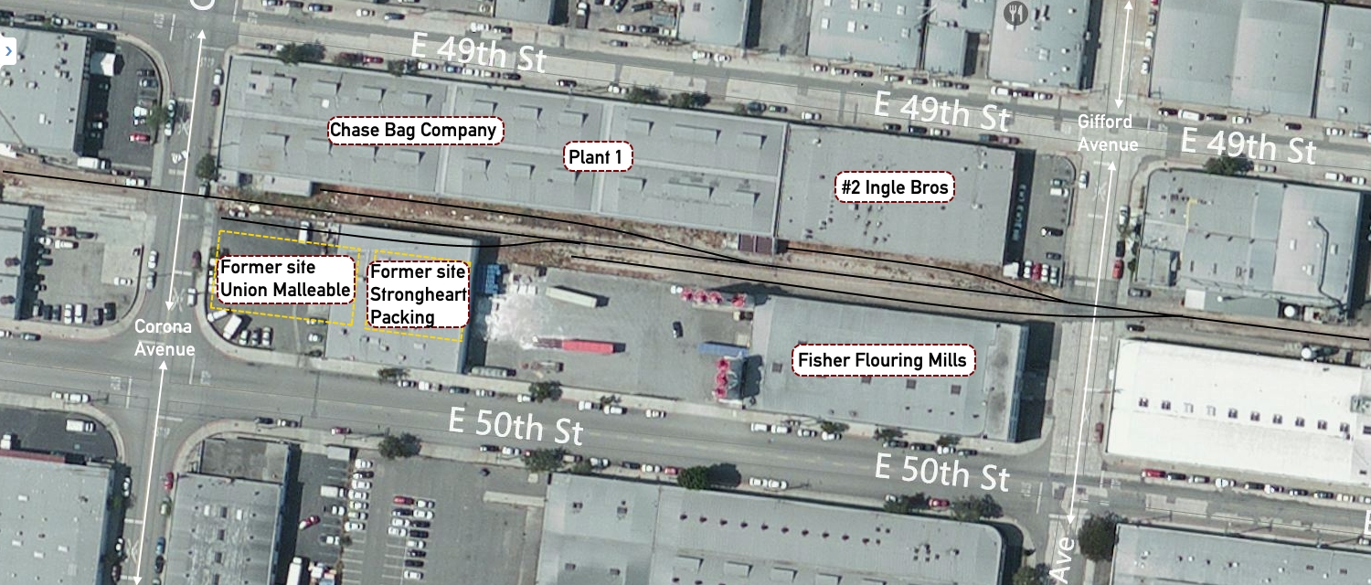
The trackage on the base of the L are to be built based on an article in Model Trains International #58, page 106 by Bruce Petty. While this was essentially an article on scratchbuilding the Strongheart Packing Co. there was also a track diagram included. While I cannot post the magazine article here for you, I can point you to Bruce’s website which has the same information and track diagram (link here)
The current track layout in this area bounded by East 49th and E 50th Street is somewhat different from that of 25 – 35 years ago, this is reflected in the two images here:
Image 1: Block bounded by 49th & 50th Street, and Gifford To Corona Ave
This is an overhead view of the same block as in the article, but several of the buildings have been removed; specifically Union Malleable and Strongheart Packing. Otherwise the track for the most psrt seems to be intact.
Another overhead view showing a slightly different angle that puts the article map in perspective.
I’ll be leaving building’s in place at Ingle Bros. It is a nice, generic building, plain brick that will be easy to model. It will have the two car spots as on the plan. The Chase Bag Co will go. In it’s place I’m going to put a team track. This will ensure that I can have a range of cars in that spot, and in addition give a great view of the remainder of this section of the layout.
The other buildings will be changed slightly to give that 1970’s renewal look of tilt-up concrete construction so prevalent in Texas.
Industry occupancy
Just as for the yard, I do not want to flood the industry tracks with cars. There are two reasons for this:
I like that industries are not always blocked with cars – this is also very prototypical, and
I am aiming at maximum to have industries be 50-60 percent occupied
Thus the total car numbers of the main board will be:
Industry 1 holds on average 2 cars with a maximum of 3 cars
Industry 2 holds on average 4 cars with a maximum of 5 cars
Interchange holds on average 5 cars (rounded up from 4.5) to 7 cars.
As noted earlier it can clear up to 9 cars at any one time if needed; this ensures that the interchange and the yard tracks should never be flooded with cars to stop the operations of the railroad.
The industrial park (bottom of the L) boards will hold on average 7 cars using the same occupancy rate. In total then the maximum cars in and out of the layout (should all of the occupied spots be switched on one day) would be 17 cars. Luckily that is not going to happen because these car movements would be spread over 6 days.
I am hoping the average will be in the range of 4-5 cars per session. This meets my goal of a short switching session, but with plenty of interest for me as the crew. More on this later.
In my last post (Why I chose not to design my layout – part 1) I discussed some of the reasons for ‘eyeballing’ my new layout and not ‘designing’ my new layout. This time around I wanted to clarify any uncertainties around the design process, and continue on with some meta-data about the design to help me clear my vision of the layout and the eventual role I’d like it to take in the future.
The Mod. 1, Mark 1 Eyeball
There is nothing better than eyeballing a space, and understanding how all the elements fit together. Obviously it makes the process easier if you understand what you aim to make, and have a sense of perspective on the amount of track you can reasonably have within the bounds of the layout space.
The layout’s story
My layout’s story revolves around switching within an industrial park. Service delivery is the primary focus of the layout and thus switching is the primary activity of the layout. With the design I wanted to be able to have a train:
arrive from the class 1 partner (interchange track),
be brought into the industrial park (switching yard),
switched into job lots for delivery within the park (customers), or to off-spot storage (storage yard),
run out to the customers needing switching that day, switch the site and then return to the yard,
have outbound cars switched and readied for delivery to the class 1 partner, and finally
have the outbound cars switched to the interchange track
Because I expect to have multiple small operating sessions each week, independent jobs that allow me to complete a little part of the operating session (between 30 – 50 minutes) each day I need a layout that supports that kind of operation. Should I manage to get a couple of people over who want to operate a full session, we can simply pick up the next job sheet and continue on from where we started.
Why the design I’ve come up with?
A multiple industry layout was always my goal since I decided to build another layout in 2003. You can see some of these layouts in the Layout Design Gallery (Offsite Link), or directly from the ‘Resources’ section below.
I read about the Modesto & Empire Traction in Model Railroader many years ago, and have a lot of research on them. But as we don’t own our own home I am loath to build something bigger than my current proposed layout even semi-permanently at the moment. So I’ve gone down the path with my own module design, that can be added to over time. Another influence was the Progressive Rail layout that MR did several years ago. Again too big for me, but there is a core of the operation that I can mimic in the space I have.
In the next post ‘Why I chose not to “design” my new layout – part 3’ I’ll review my ideas on the operational aspect of the layout; the proposed paperwork that I want to use. It’s getting late and Sons of Liberty is on the Tele tonight. From Ballarat, on a cool and clear evening – good night.
I’ve designed a lot of layouts over the years, because I wanted to and because I got paid to. With my new layout though I wanted to take a more organic approach, one that relied less on the ruler and more on the eye.
Apparently I’m not the only one following this process. Over on Lance Mindheim’s blog, he recently wrote in a post that (offsite Link Here) – “… with a smaller project a lot can be accomplished in 1:1 scale simply by mocking things up full-scale with boxes and loose pieces of track. The elements can be re-sized and moved around until you get the look that you want…”
I know exactly what I want this new layout to look like. I know the signature scenes I want to include, and I have my set of wants that have to be included to make this enjoyable for me. Sometimes you simply cannot beat the mod 1, mark 1 eyeball to tell you when you’ve hit the mark.
It’s all about the operations
Over the last couple of months I’ve played around with the physics on my DCC & Sound equipped engines. When I’ve times the sessions using an old Tablet computer set aside specifically for that task, what I’ve noticed is that when running prototypically, that is with slow switching speeds, easy moves, and time between moves to allow the offsider (a conductor, or second person) to do their work, eating up 20 minutes is very easy.
To enjoy an operating session I have to be actively involved in the doing of the work. To do this I have made changes to freight cars that I’ve found have a profound effect on how I work. For example; I’ve brought average car weight up, close to the Cubed-Root (CR) of the real car. You might not want to do this if you are running plastic trucks and wheel-sets or have cars traversing long distances as wear and tear will show.
Coupler Bounce what the … ?
With Kadee equalised metal trucks and metal wheel sets I’ve noticed a complete change in the physics involved, and that is what I had hoped for. So when I couple up to a single freight car with a CR close to the real weight you do not get what I call coupler bounce.
Coupler bounce is where the car takes off in the opposite direction (thanks Sir Isaac) when a locomotive pushes up against the car’s coupler face. My lighter freight cars continued to do this no matter how lightly I pushed up to couple on. The added weight causes friction in the Kadee truck journals, and physics come into play such that the extra CR weight requires more energy to get moving.
As I convert cars over to Kadee trucks I’m making sure that I CR the weight to make sure I get better handling characteristics. I know that this flies in the face of the accepted practice, but once you see this in action, especially in a longer string of cars when the slack runs out, you can never go back.
It’s all in the switch action
I love working yards, and switching industries. I was born to play at doing this. It keeps me happy, and engaged, and with many locations to switch, that are independent of each other I will never get bored with the challenge of switching a layout with multiple customer spurs and car spots.
I love the down and dirty, first mile, last mile railroad action that you find in customer switching. With a marshalling area that allows me to make up trains for delivery to interchange, and break down trains for delivery to customers and I’m about as happy as anyone can be.
In part two of this particular rant, I’ll talk more about the operations and paperwork that I’m going to use on the layout. For now, the sun is out, the wind is very cool and all is well in Ballarat. So I’ll leave you to it…
It’s all operations Saturday, thanks to Martin Hogg, the owner and operator of Brett.
Site 1: Brett – a full operating session video
Martin Hogg’s released a new video (Brett’s been featured recently on the blog).
This time you get to see a full operating session from start to finish.
This video shows just how much enjoyment you can derive from switching on a relatively small layout with a reasonably simple track plan.
I’m guessing the operating session lasted around 25 – 30 minutes from start to finish. As soon as I get some feedback from Martin I’ll update this post and let you know for sure.
Good work that man! On you Martin.
Update 1:
I talked with Martin Hogg today and he confirmed that the operating session takes about 25 minutes (although he says its heard to be sure as he was busy phaffing around with the camera to be sure). He’ll be running another session to confirm that but I’m pretty sure that it’ll be right around the 25 minute mark, depending on the work to be done.
I’ve known Chris Gilbert for many years thanks to the Internet, specifically RMWeb. Chris has always managed to be a great mentor on things model railroad, even if he was not aware of his mentorship. He’s been successful in building, exhibiting and publishing a range of model small exhibition layouts over the last several years. What gets me is how quickly he puts these model marvels together.
Florida Springs (V 2.0) – An HO Scale exhibition layout
Chris in his own style said that he started the layout on Tuesday the 10th of February with a trip to his local hardware store.
Within five days he was at this stage:
As if that was not enough to make me feel like I need to pick up my game, his detailing is exquisite. If you take a link at post number 5 (link here) you’ll see what I mean.
Every time I see what Chris can do in so short a time, I am simply bowled over. He thinks about something and then he gets it done. It’s something that I am going to aim for in my modelling this year.
Before I can get there though I have to complete some other modelling projects to finish for my local model club show in April (you can read more about that on the Modellers of Ballarat blog (link here).
I’ve listed other sites in the resources section below. Enjoy having a look at Chris’ layouts. They really are magnificent works of art.
Resources
· You can find out more about the O scale Fort Smith Railroad layout (External Link) here.
· You can visit Chris’ YouTube channel (link here) – and watch his videos of Haston and North Haston – great stuff.