Category Archives: Layout Design

Layout Design, and Designs

A tuning fork just begging to be modelled

Introduction

If you have not seen a tuning fork layout, it is a very simple 1 turnout operation. If you are still not seeing it in your mind, think of the letter ‘Y’. Most of the layouts I’ve seen assume either a mainline and a siding, or two sidings. However, that does not mean little operational potential. I found a video by Thornapple River Rail Series on YouTube [Link is below] this week and it got the creative juices flowing.

Packaging Corp of America - Grandville MI

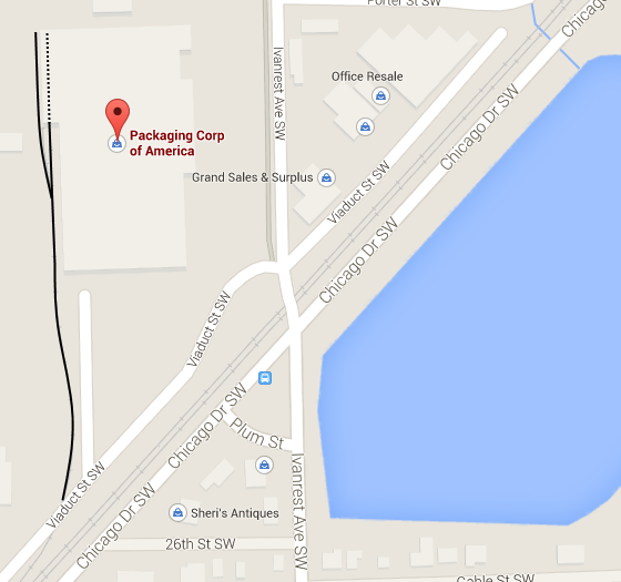
Image 1: The location of the facility from Google Maps

The kicker is that the second of the spurs is used to allow switching to take place on the spur itself. Before you do any more reading watch the video (It is 18 odd minutes long but if you start at about the 4:36 minute mark you’ll get the gist pretty quickly).

Video 1: thanks to Thornapple River Rail Series

Operations

If you start at about the 4:40 mark into the video you’ll see the following occur:

  • Loco and first three cars cut off from the train
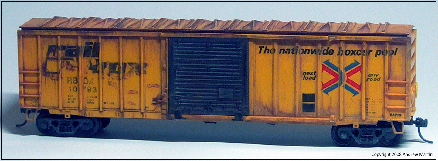
  • Same pulls forward of the spur switch, and reverses across Viaduct St SW toward the plant
  • You’ll notice the second spur on the outside of the plant as the train pushes back toward the plant
  • Once the roller door comes up, the train pushes back into the dock area, picks up the outbound cars, and pulls forward again to clear the switch for the spur
  • Next, the outbound cars get pushed onto the exterior spur
  • Inbound cars get pulled forward onto the spur again, the switch is reset, and the inbound cars are pushed back into the dock
  • Loco cuts off, pulls forward to clear the switch, and once changed over, pushes back to hook on and pump up the air on the 3 outbound cars
  • Pulling forward the loco and three outbound cars cross over the road and re-join the train
  • Just to add the cherry on top, the train then reverses back to the yard with the engineer riding the caboose

Now all of this takes between 10 – 14 minutes of video time. But what a fantastic way to spend your 5-20-5 minutes of daily modelling / operating time (read a post on that concept here).

If you want to make it last a little longer, first re-arrange the incoming cars into the order as required by the plant. Additionally some cars may not be unloaded yet, and they need to be moved off-spot, and then back on again with new inbound cars. Some cars may need to be left off-spot on the exterior spur for the next switching session.

Layout idea

While I mainly model in HO my true passion is 0 scale (and bigger when I can manage it). Alas I have not the room for a big layout to run those sized trains – yet.

The layout - via BING Maps

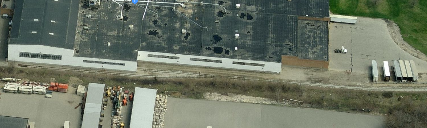
Image 2: The complete layout (click for a larger version of the file)

For an 0 scale layout I cannot think of a better idea. You could easily do that in 12 feet and no more than 12 inches wide. If you really had the room you could do it in 18 inches wide and go nuts with weathering, winter trees as in the video, and the knocked over Armco barriers. Glorious! The big gotcha here is that the switching lead ahead of the switch has to be longer than 2x the maximum number of cars you switch into the dock. Don’t forget to add a loco length on top of that too.

So if you switch in 3 cars and out 3 cars you’ll need to have six spots plus a loco length to allow the switching to take place.

Hope that this gets your creative juices flowing. And thanks to Thornapple River Rail Series for posting the video. I am going to be looking through a bunch of his videos now for other similar ideas for my layouts in the future.

It’s a sunny and pleasant Saturday afternoon in Ballarat, hope you’re enjoying your day where you are.

Resources:

Google Maps: Location

Bing Maps:     Location

Brett – a great small layout you can model

Introduction

When you travel for business, you can spend a lot of time staring at the walls of your hotel room. While travelling in June of 2014 I came across Martin Hogg’s YouTube channel and his switching layout – Brett. Martin has built one of the best operating layouts for a small space. 8 feet long and 1 foot wide it packs in plenty of switching while allowing short, focused operating sessions that you can set up and run any evening without a lot of effort.

Martin’s Videos

Here’s Martin’s first Video:

In November 2014 Martin posted another video:

In November I was lucky enough to catch up with Martin; I wanted to find out what had been his inspiration and focus for designing Brett.

Designing Brett

Previously known as Dreary, Martin’s layout has been renamed to Brett after a recent revamp. Still set in Idaho in the early 80s the layout is at the end of a branch line, now under the ownership the Yellow Pine Railroad (YPRR). Essentially a run-around loop, with industries off each end of the loop and an interchange track, trains enter from front right and loads are spotted at industries according to the crew’s switch list for that day.

Martin says that his attention has wandered recently and that the railway had taken a backseat to other modelling interests. “I decided to re-vamp the shelf layout. I have various plans brewing for another American one, but I decided to try to get some more out of this and I have to say, so far it is working.” The layout is essentially a loop with sidings.

Martin says that “there was no room to have a traditional staging or fiddle yard”.

“The track at the front right acts as the ‘interchange’ or in/out track.”

Operating Brett

Early on in the design Martin decided that “there was little point in creating an illusion of ‘somewhere else’ as this layout wasn’t going to be leaving my spare room. So the front track acts as the on-scene staging and provides the start and end point for the game play.”

The loop in front of Smith & Hogg’s track can contain a maximum of three 50 foot cars, Northwest Lumber can  handle 2 cars, and Farmers Co-Op can handle up to three 50 foot cars, while the team track and Smith and Hogg can manage a single car each.

The aim of the game Martin says is not to overload the layout with too many cars. Martin prefers to switch a couple of cars for 30 minutes at day’s end, rather than spend a couple of hours once every now and then. Additionally only having to setup a couple of cars means it is faster to set up and tear down an operating session at the end of the working day.

“I planned to allow 1 loco+2 cars (or 3 cars) as an ideal length for each spur to allow switching moves. The ‘interchange’ or fiddle track at front is the same.”

Industries

There are four industry spots on the layout. From Left to right they are:

  1. Team track
  2. Northwest Lumber
  3. Smith & Hogg Hardware, and
  4. Brett Elevator (Farmer’s Co-Op)

More information

Would you like to learn more about Brett and Martin Hogg? You can download a full article by clicking here: Small Layouts: Brett – A switching layout design

Updating Athearn Blue Box Railbox XAF 10 cars

 Part 1 – No plan survives first contact with the enemyThe basic blue box car

It has been some time since I’ve had the funds or the time really to do much of anything in the modelling realm.

I’ve simply not had the funds to bring a lot of the work I’ve had underway forward to completion. Thanks to the Taxman and a payout due to being laid off, I’ve been able to order some extra parts to complete most of my Railbox cars.

The most important of all the parts has been a set of Microscale decals.

I ordered these from Microscale in the US and very quickly in the post I received 3 packets of Microscale (87-1291) HO scale RBOX & ABOX decals. Microscale’s service was fast and excellent after ordering directly from their website. They decal two cars of each type and come with all the car data you need for the cars.

RBOX_Microscale_Decals

I have a lot of these cars to re-work; at last count I believe about there were 10 in total. I have enough to cover 6 cars for now. With my layout that I’m building (currently set in 1978) there’s latitude for the Hunter Valley to have bought some similar per diem boxcars. These cars I’ll complete last as I have to produce or manufacture my own decals for them.

Updating the Athearn Blue Box model

The Athearn model is, except for the roof pattern used, correct for the XAF10 series cars. The kit does not have the detail that modern-day kits come with as standard, but they were only $7.50 when I bought them and even after the upgrade process will top out in real dollar terms at less than I can buy the newer models for now. To keep the costs down I’m making most of the add-on parts. To be fair I love scratch building. It has always been my favourite part of the hobby.

Let me say this before the rivet counters jump in: I know that the roof panels on these cars are wrong, I can live with that. At the height above the floor the new layout will be, they really won’t be all that obvious,even if they may be easy to see.

When money is tight these simple upgrades make all the difference. What other issues remain I can live with. There are some issues though that I just cannot live with. In order of descending importance they are:

  • Trucks – I replace these on all of my Blue-Box cars. In this case they’ll be the 70 ton roller bearing trucks (fully equalised) by Kadee. I love these trucks, and with proper weighting they run like a dream floating along and bending to the poor track of the HVL (we are a ribbon in the weeds kind of Shortline you know). At around A$15.00 per pair they are not cheap, but they work so well I’ll eventually fit them on my entire fleet as I can afford to.
  • The body side the grab irons just irk the hell out of me; moulded onto the body side and just begging to be milled and replaced with brass wire – the image below shows the experimental car with these.modifications. While the grab-irons on this model look over sized I am certain that once they’re painted they’ll stand out a lot less. If they don’t then I’ve since sourced some really fine brass, and if they aren’t fine enough I can always get some fine copper wire, tin it and then fit them for prototypical accuracy

Modified_Bluebox_Boxcar

  • The stirrups on the car ends are OK, but I can do better using brass wire, brass strip or as shown in the image above good old-fashioned staples (which have proven to look great but will need to be drilled, glued and then have NBW castings glued through them and into the body to stay on – every one of them has been knocked off  – even with careful handling and using the best super glue)
  • Updated Kadee knuckle couplers (I prefer the #58 which have a much finer head casting). From these I’ll  be removing the magnetic glad hand as I do all of my uncoupling with a skewer, and because I’ll be adding air hoses and glad hands (these magnetic units which look really great as you can see in the YouTube video below. They are now available from P.W.R.S. at: http://www.pacific-western-rail.com)

Remember how I said no plan survives first contact?

If I were a purist, or a glutton for punishment, I could rework the car ends. There is much that could be done by milling the ends and cleaning everything up and starting again. I just can’t be bothered. The ends are good enough, and because they’ll be in between other cars, and generally not focused on I’m not going to worry.

The coupler box used on the model is wider that the real one used on the real car, but again, this is between the cars during normal operation and really, I just don’t think it matters. I’ll live with it.

In part 2 I’ll provide a historical context to the build, and then in part 3 I’ll move on to reworking the basic car into something better for your railroad, and mine.

Progress Rail in Waycross Georgia –

As someone with little space, and limited funds to put toward layouts, I am always looking to find that next great small layout idea. With my role at work coming to an end unexpectedly this week, a small lower cost layout is even more important than ever. While spending some time getting to grips with redundancy I was idly looking at image sites when I came across the Progress Rail facility in Waycross Georgia.

It is a great little facility that has storage for the locomotives coming in to be worked on or scrapped, and then a couple of simple buildings for work to be done. The layout of the track is very simple too. I’ll post updates on this post with additional images once I’ve completed the work on the images.

For now you can look at the following links here:

Videos:

Images:

I’ll post a plan and some other images I’ve found here soon.

Andrew

A Short History of the SP/SSW 40 foot Hi-cube boxcars and notes on modelling them

Introduction

[Last updated April 10 2025]

The forty-foot, 70-ton, Hi-Cube boxcars were built in the mid-1960s specifically for high volume, low weight cargo and were most often used in captive service between appliance manufacturers and distributors. They occasionally branched out into furniture and paper loads. Manufactured by Pacific Car and Foundry and Pullman-Standard, ultimately, their small size and the load limitations this imposed saw them leave the rails in a relatively short time. Other larger boxcars from around the same era continued to ride the rails when this article was written (Editor’s note: August 10, 2010).

The forty-footers were a stop-gap car, never meant to have a long life. They provided shippers and receivers with a means to utilise their existing dock and door spacing for 40-foot cars while allowing double-layer (vertical) loading of refrigerators and freezers. From an economic perspective, this was a win-win. With less money spent on new boxcars and upgrades of current boxcars than would have been required on new facilities, doubling the number of refrigerator and freezer units shipped per car made economic sense.

US appliance companies such as Amana, Maytag, Whirlpool and others would, within a decade, begin upgrading their manufacturing facilities and receiving warehouses as older ones were closed or rebuilt. As a result of these upgrades, 60ft High-Cubes, which could haul a vastly larger load, became the norm. However, there is photographic evidence of the cars riding the rails until at least the beginning of August 1984. I have seen photos showing one of the cars in revenue use in the early 2000s. Some served in paper service and maintenance-of-way (MoW) before retirement and eventual scrapping. Sadly, none to my knowledge exist in railroad museum collections.

Southern Pacific and Cotton Belt B-70-36 Box Cars

My primary interest is in Southern Pacific (SP) and Cotton Belt (SSW) hi-cube box cars, which were all built to the same design by Pacific Car & Foundry in 1966 and 1967, featuring a 5001 cubic foot capacity, Hydra-Cushion underframes and 10′-6″ Youngstown sliding doors. These cars came to be nicknamed the “Ugly Ducklings” due to their awkward appearance.

Intended for captive appliance service, their internal dimensions were 40′-6″ long, 9’ 6” wide and 13’ high. This allowed double stacking of freezers, allowing greater loads than regular boxcars. Until their introduction, the second layer of freezers was laid on their sides. This led to problems with damage to the second layer from train handling.

Externally, the cars had an overall coupled length of 45’ 5”, a maximum width of 10’ 8” and stood at their highest 16’ 10” above the rail height. It should be noted that the 1969 ORER shows the 11 SP cars one inch higher at 16’ 11”. A roster of the class B-70-36 Hi-Cube box cars for the Southern Pacific (SP) and the St Louis Southwestern (SSW) or Cotton Belt is provided in Table 1 below:

Road    Number Range    Number    Load Specific Data [1]
——————————————————————-
SP         659100-659111        12        DF-B loaders
SSW    36014–36026             13        DF, DF-B, Car Pac loaders
SSW    36027–36081             54         As Above
SSW    36082–36120             39         As Above
SSW    36121-36126                6         As Above

Total Cars:                           124

Table 1: Southern Pacific Railway System 40’ High-Cube data

NOTE: The Cotton Belt had another set of Hi-Cube cars (SSW 36000-36013) not covered by this article. These were rebuilt from cars in the SSW 33850-33949 series built by Pullman-Standard in 1951. Their roofs were raised and they were given new 10′-6″ wide by 11′-9″ tall doors. These cars were converted at Pine Bluff between December 1965 and January 1966 [2].

Operationally, the Cotton Belt (SSW) had the lion’s share of these 40-foot cars. It would appear that they were delivered in four different lots during 1966 and into 1967 that, while consecutively numbered, were given different listings in the ORERs of the time.

Modelling the 40-foot Hi-Cube

NOTE: It should be noted that these cars were few in number and in captive service between the major white-goods manufacturers and the regional distribution locations.

Built from the mid to late 1960’s they appear to have all been off the roster, or in MOW service (thus out of white-goods revenue service) by the late-1980s. recent research has shown that some went into furnitures and paper service.

Having said all of that, if you love these cars as much as I do, for a small layout or just want to have a few on your layout, the details below will be of assistance to you.

Athearn

  • The cars manufactured by Pacific Car and Foundry for Southern Pacific (SP) and the Cotton Belt (SSW) match the Athearn exterior-post model. (#1950 40′ Ob Hi-Cube Box Car – PC&F for SP 659100-659111; SSW series 36014-36126, both class B-70-36) fairly closely
  • The UP’s home-built car, which was not covered in this article, closely matches the Athearn plug-door model; these also match the rebuilt cars of the SP. (#1960 40′ Plug Door Hi-Cube Box Car – UP class B-50-4 appliance car)

Bibliography

  1. This data was sourced from the January 1969 Official Railway Equipment Register.
  2. Source: for more information please visit:
    1. For SP and SSW cars, see: http://www.railgoat.railfan.net/spcars/byclass/box/b070-36.htm
  3. See https://tycotrain.tripod.com/id28.html (updated link to the same information, just on a different site)

More on the new layout

Originally posted on the old DasBlog – Thursday, March 28, 2013

While I am not working on the layout of a weeknight, doesn’t mean that I am not thinking on the layout.

My son Ewan (who is 8) got me to thinking about a new layout after a Sunday morning spent switching on a plank I have setup for testing car and coupler heights and and so on. He enjoyed it so much, big smile – the works, that he asked me to build something bigger because he liked driving the loco up to the cars and switching and coupling/uncoupling the cars so much.

He is a mad gamer, and is asking me to help him learn to code so that he can write his own games. So I figured why not make sure that he could “role play” with the locomotives and cars. I have spent quite some time getting the physics of the locomotives right in the decoders and this has formed the basis of my thoughts for the new layout.

What I have currently

I have the following DCC loco’s:

  • 2 x Bachmann 70 Tonners (cause I love them – one in Red and the other in Green – and yes they are noisy enough without sound – working on a fix for this in the future)
  • 1 x BLI Trackmobile (which moves like honey in summer it is so smooth and oh-so-nice to switch with…)

I have the following DCC & sound equipped locos:

  • 1 x BLI EMD SW7 (in UP colours – my Wife’s favourite scheme)
  • 1 x Proto 2000 GP20 (also in UP colours)

What all of this means to the emerging layout design is this:

  • Long runs where ever possible: This allows the physics that I have programmed into the locomotive’s decoders to come into play. For sound equipped locos I have made sure that the SW7 takes a shorter time to load up before pulling away. This simulates the locomotive gearing, while the GP20 takes longer to load up before moving off for the same reason. Once a loco is moving, having watched a lot of videos on you tube, the power is usually cut and the loco coasts. I can now do the same thing with the Deceleration set reasonably high to ensure that the loco will slow if going up a grade, and maintain or speed up slightly when going down grade. When I need to stop I give a brake application (F7 on my MRC Prodigy Advanced 2 system) whence I get brake squeal, and the locomotive and train stop where needed.
  • Proto weighted cars where possible: I use Kadee trucks This ensures that the cars track much better than NMRA weighting standards. I use Kadee trucks under all stock and it they run much better when they are weighted properly to compress the main springs. I use a cubed root formula spreadsheet to track each car type and the weight they should be carrying. One nice side effect is that the clickety-clack as trucks go over rail joints sound much better in my opinion.

One location that is getting serious design time right now is a Miami Transload Facility. My version would only have three tracks in the Transload facility, the centre one being an overflow (99 off spot according to the SP) track that would also increase the switching.

In the background I am still thinking of adding the bakery that Lance Mindheim wrote about. This effective uses one switch for two long sidings. This would allow the two locations to be switched separately, but different operators that are still within arms reach, and yet still stay true to the area they are modelled on.

During my original planning I had though of extending the design from the 12 foot board through to the 8 foot return board, and using a rotating sector plate (rotates completely through 360 degrees) on the final four foot board with an overhang to provide staging.

Still thinking this over as well as the Boxcar Haven design. More thinking at the moment, will yield a better design in the end. Thanks for following the internal monologue; any comments are always welcome.