All posts by Andrew Martin

A long time technologist turned Melbourne tram driver, I'm focused on sharing my knowledge on a range of topics including food, technology, scale modelling, and crafting. Enjoy the content and share the ride by subscribing, and commenting.

O Scale switcher – the longest project in modelling history

In the beginning…

A long time ago, in a modelling landscape far, far away… there was a UK Model Trains magazine (I cannot remember the issue) that described the conversion of the Atlas O scale Plymouth switcher; the aim being to turn it into an industrial UK shunter.

If my memory serves me well it would have been about 1982 or there about. In short order I found myself owning four of these locomotives, and set about modelling the shunter as I’d seen it a couple of years previously. Having said all of this the title of this article now becomes important because I am about to finish the project that I started sometime back in the early to mid 1980s, in the mid 2010s. Yep – that’s 30 years.

That ‘Model Trains’ magazine article suggested either:

  1. Keeping the cab height the same as it was on the original model and raising the buffer beam height to allow for buffers etc. or
  2. Raising the entire cab by about a scale foot and raising the height of the footplate at the same time to allow for buffers to be mounted on the end of the frame.

I chose the second option as I wanted a snappy looking locomotive and not something half thought out that I’d never be happy with. So with magazine, (I have the copy somewhere and I’ll update the article details when I have them) plasticard, liquid glue, files and a sense of adventure I started working on the model.

I left the length of the loco as it was, and raised the body height with a conveniently wide piece of plasticard stock to get the height visually right. In reality that was the easy part as you’re just adding that to the bottom of the body.

20150205_172152 20150205_172140 20150205_172108 20150205_171852

All images are Copyright Andrew Martin 2015 unless otherwise noted

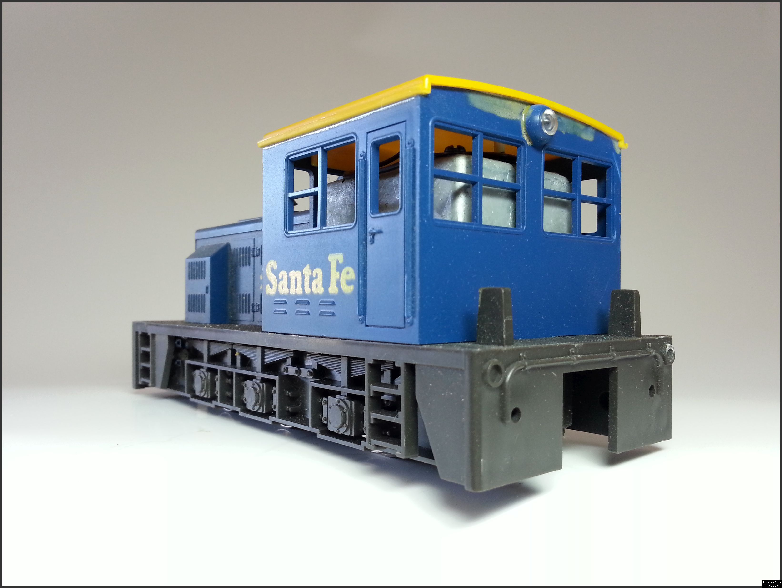
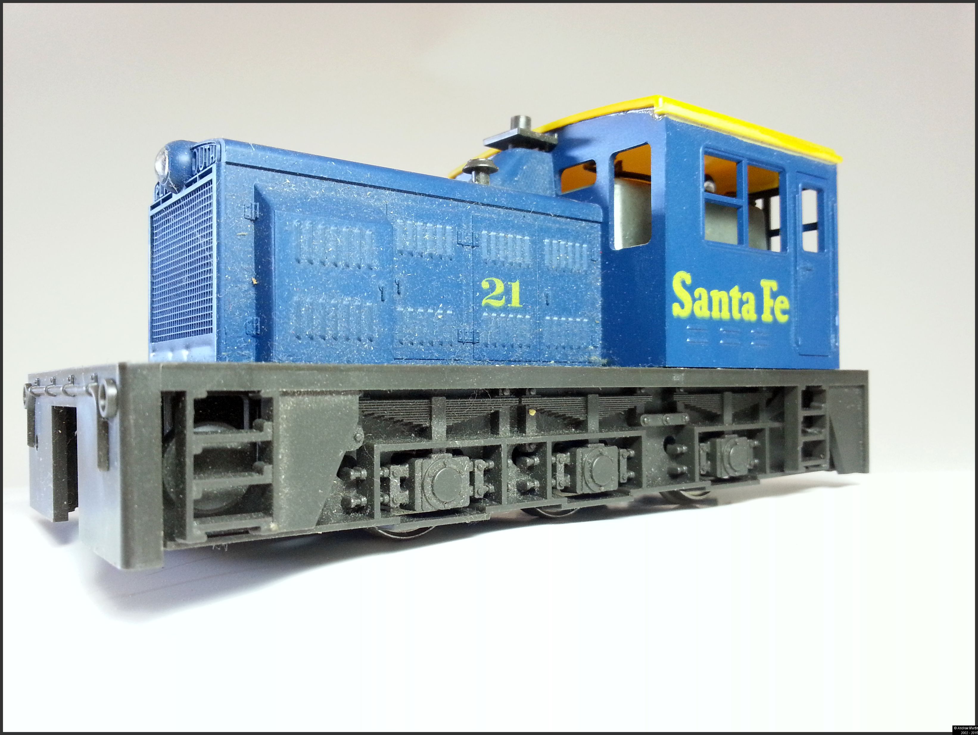
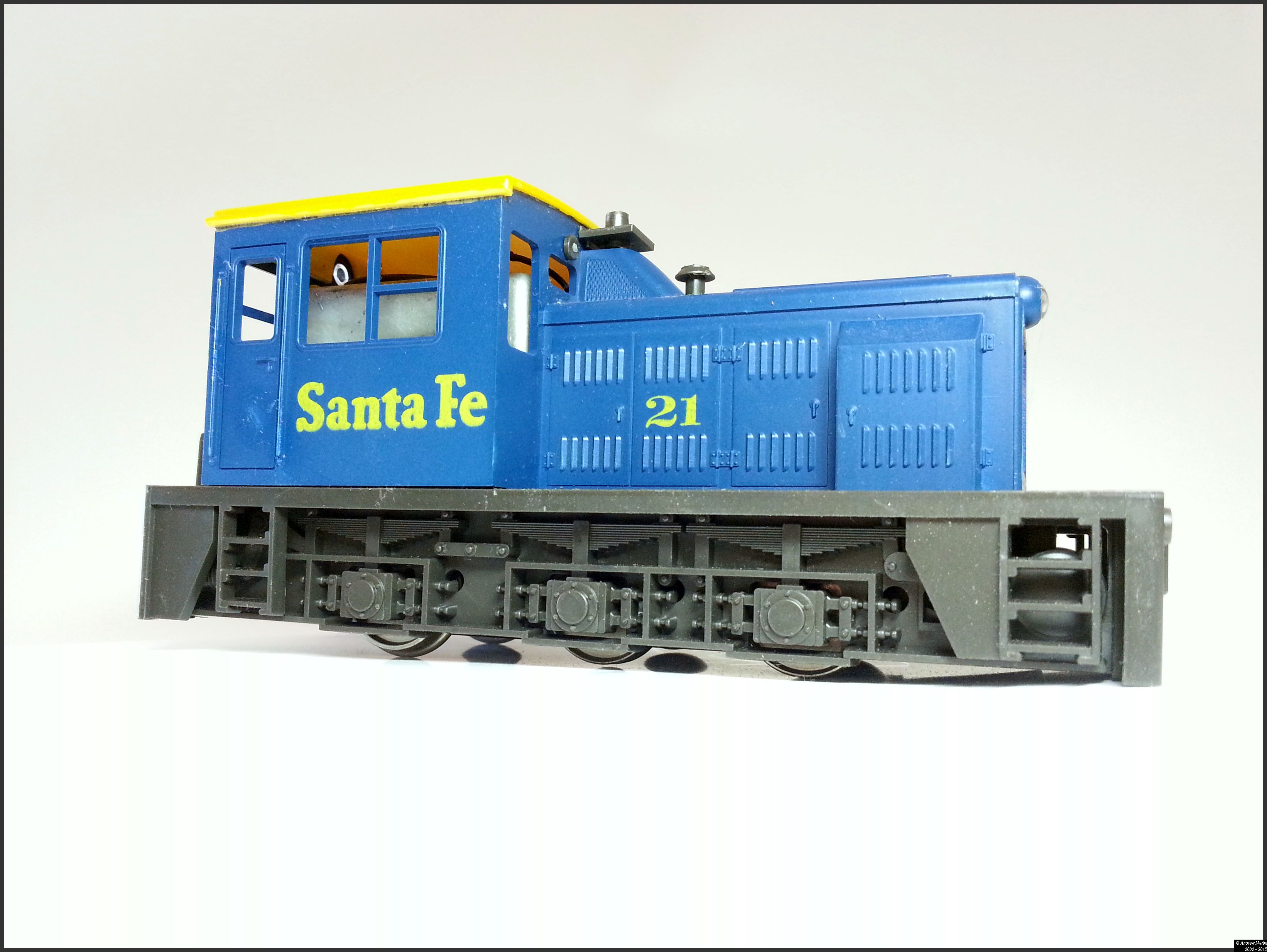
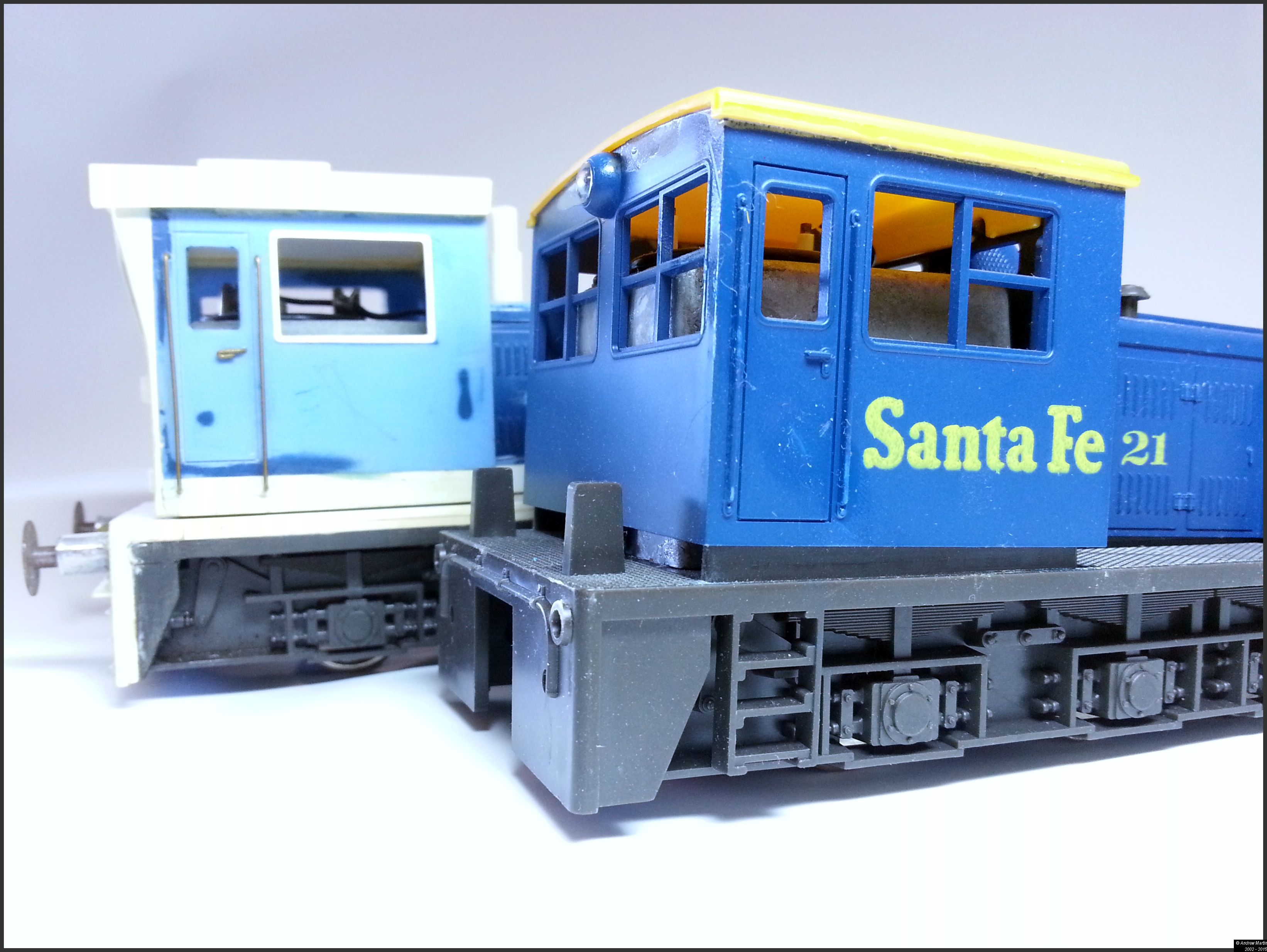
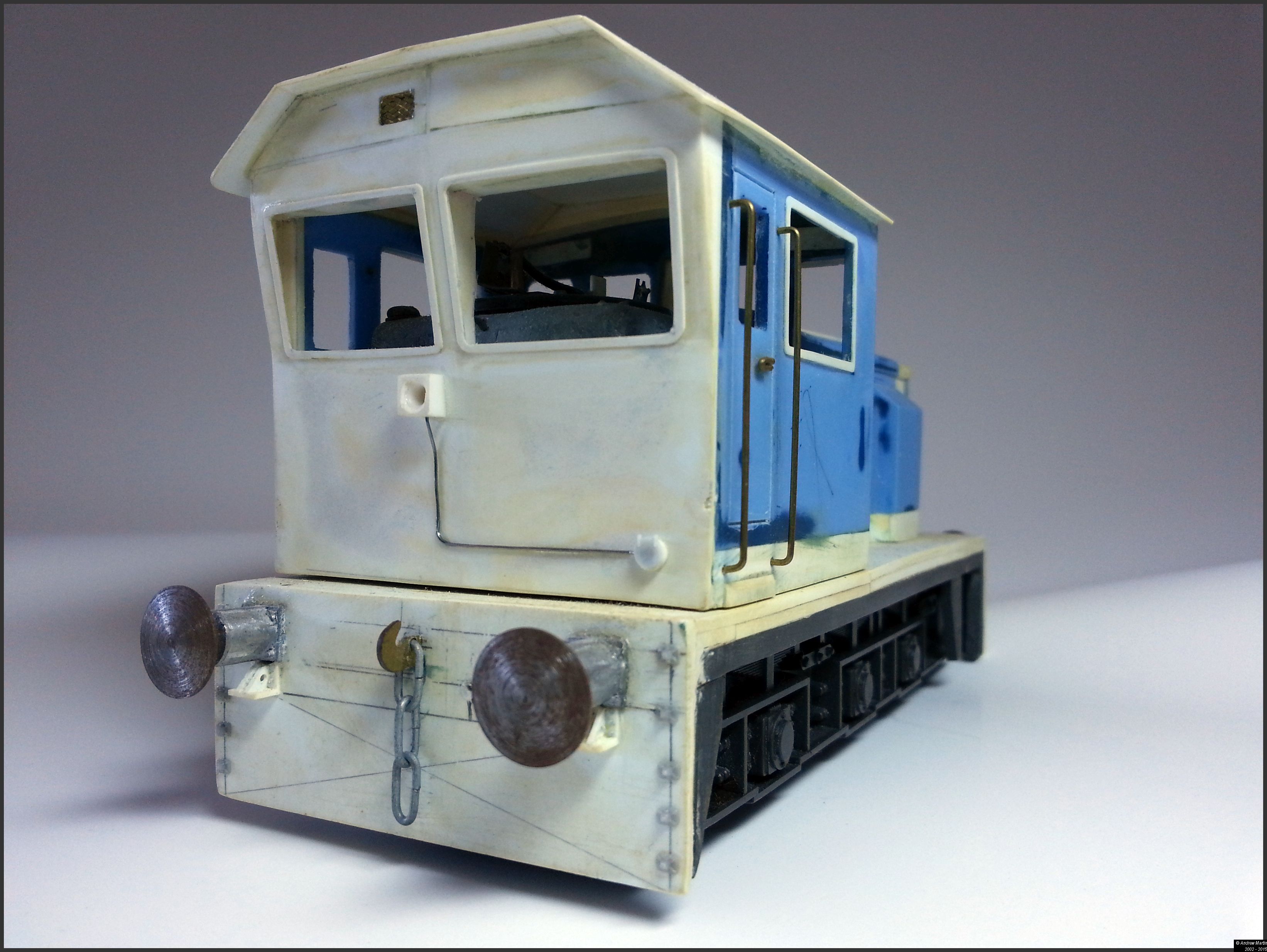
In the four photos of the unmodified model note the squat nature of the body. The last photo shows the difference in height between the modified and original loco that the two 40 thou shims of plasticard give. It should be noted that the loco models that I have come with a textured surface on the footplate simulating a safety tread pattern. This was sanded down and removed prior to installing the higher floor.

Next I cleaned up the four pane windows and made them single pane. Finally I sanded down and covered over the buffing faces on the loco ends in preparation for the 3 link couplings and buffers. The only problem was that having put all of that work into the loco – it did not look right to me. It looked like a higher roofed American loco and not something that would have been made in or for an English railway, especially a Quarry railway which I’d always wanted to model (and still do). So it was back to the drawing board.

The second coming…

Unfortunately I only have photos from the second rebuild that I started in 1996 or there about and none from that first effort as it was back in the early 1980s and I don’t remember owning a camera at the time (being a poor electronics apprentice).

Before I begin any modelling project (I over think them to be honest) I do a lot of work on how the final model will look; This locomotive was no different. First was a working sketch that I scanned recently and cleaned up below. (Yes I store all my sketches of train models.)

Modified_Drawing_O_Scale_Switcher
Figure 1: Concept Drawing – Copyright Andrew Martin 2015

There are some differences between the concept sketch and the final model that I’ll be completing in the next week or two – overall I’ve come pretty close to what I wanted. I’ve not bothered with the end rails and chain nor the MU stand. As the quarry locomotives were generally run individually and not in MU service in the UK from what I can gather. Additionally I took about 10 mm off the rear end of the unit since I did not want the air tank or a balcony on that end with the new look.

The changes

20150205_171754
Photo 1: The extent of the surgery

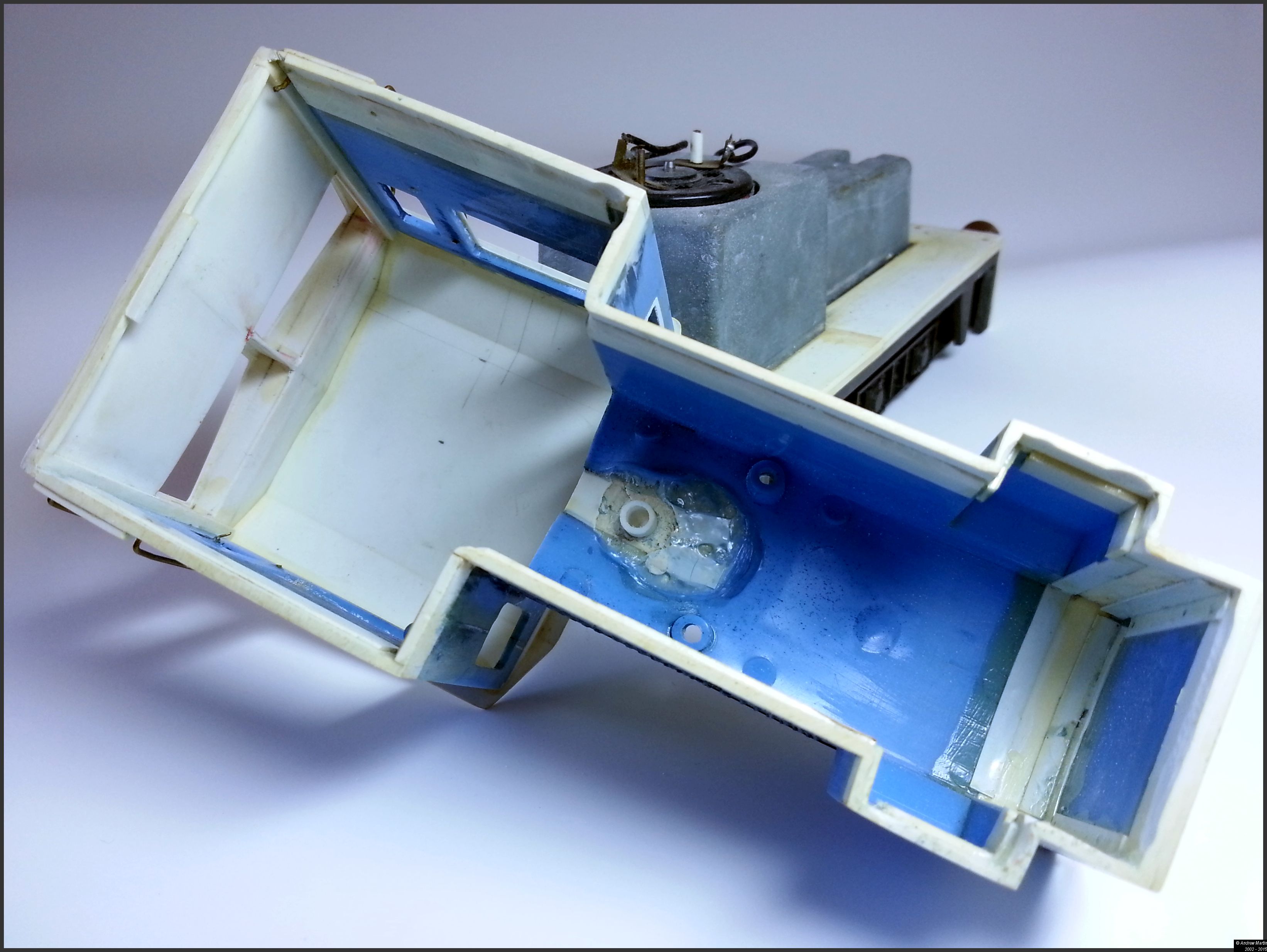
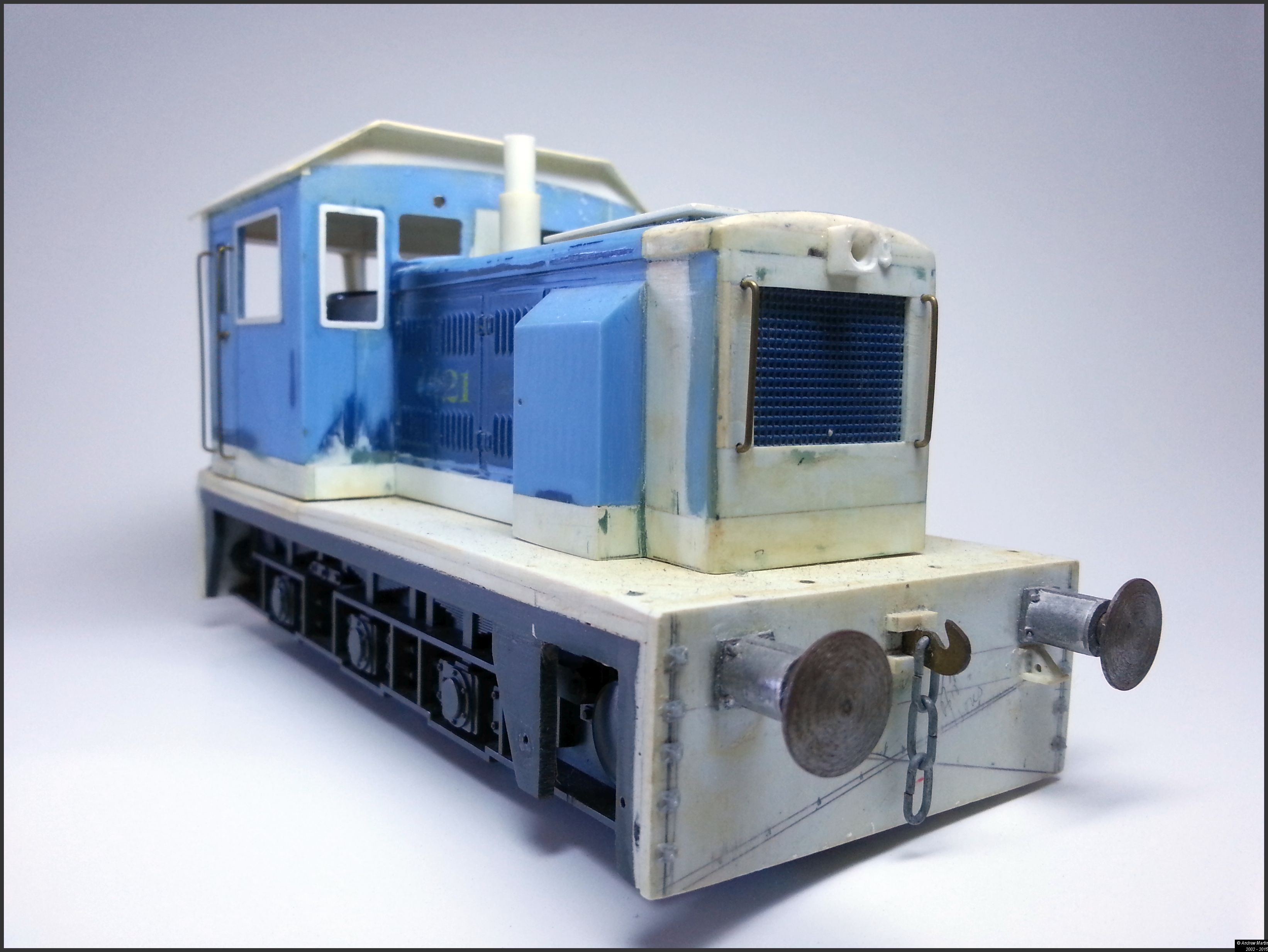
If it’s blue, it’s not new. The bubbly mess of plastic in the cab end of the hood is what happens when you try and speed up curing of putty with an incandescent bulb. The stove pipe chimney was the result of that and not planned. However, I did add 5mm in the front of the hood to extend the hood forward and rebuilt the front top are of the hood too as the bulky light on the original just irked me too much to live with. The entire cab roof, and rear wall was sawn out, and a plasticard cab end and roof was put in its place. This sounds fairly straightforward, until you see the amount of work that actually went into designing and building the new cab end.

O_Scale_Switcher_In_Build2
Photo 2: Cab end plate, and ribbing waiting for the skin to go on


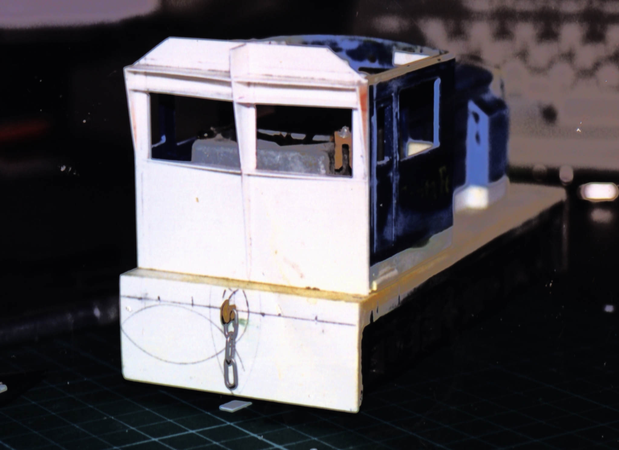
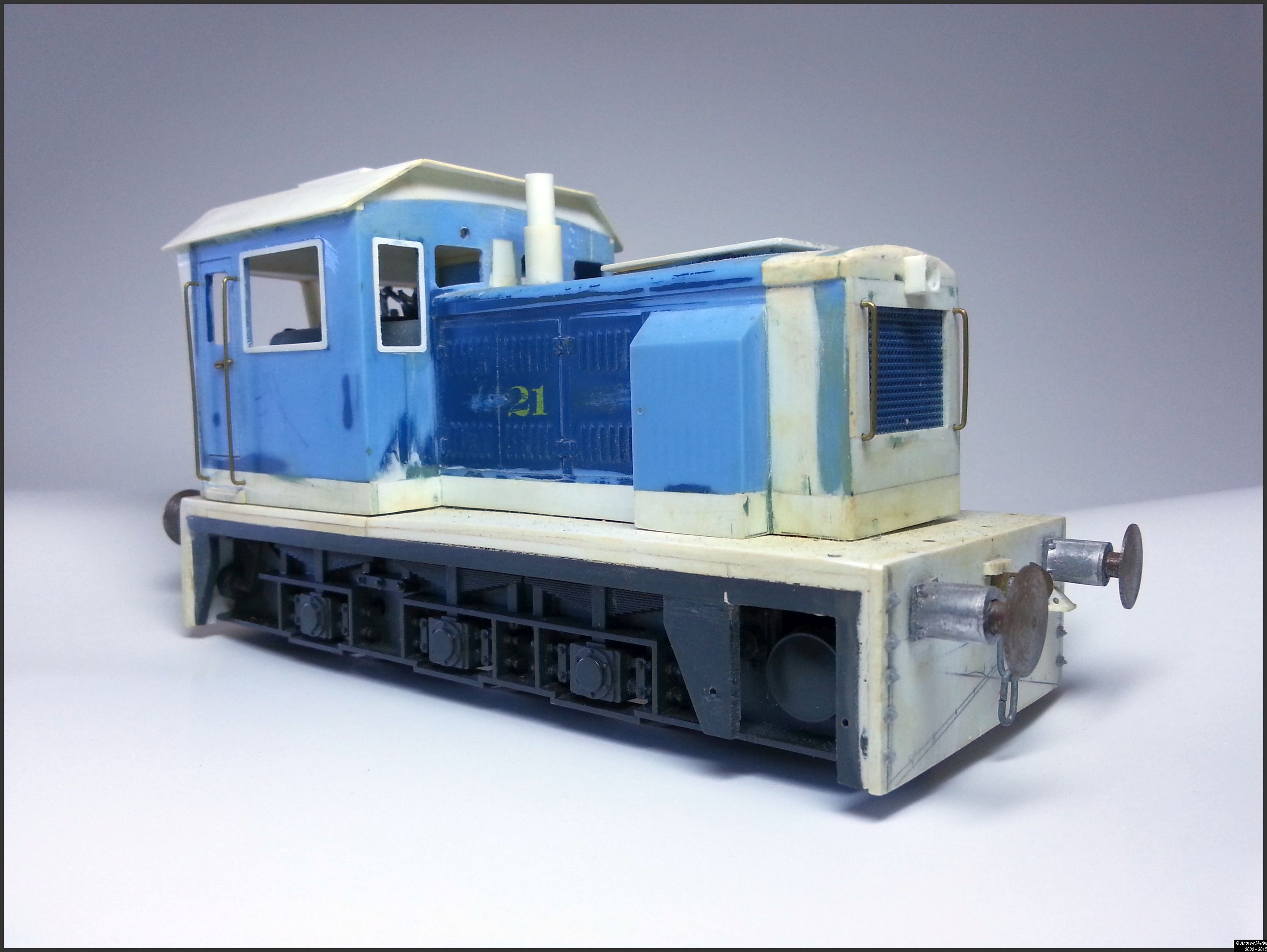
Photo 2 above shows the planning and work that went into the design of the new cab. When the skin (10 thou plasticard) went on it was measured and cut in one piece to ensure that there would be no visible seams on the face of the loco. This went off without a hitch and I learned a lot out of that exercise that has helped me in my model building since. Photo 3 below shows what the cab looks like after the skin has been cut and glued in place.

20150205_171716
Photo 3: The new cab end completed


Also in Photo 3 above you’ll note the

  • Oleo buffers (from House of O Gauge in the UK – now gone I believe). These are working buffers and work as well as they look.
  • The electrical conduit to the light is fine solder Super-Glued in place. The light is a square styrene section with a circular section cut into the square frame and then drilled out to accept an LED. This will go back into the cab and into the DCC board. I had thought about having a duel sealed beam set, but I liked the look of this better.
  • To remove the need for a rear facing horn, I cut a small slot into the top left of the cab for the horn. I’ve yet to place a horn placed on the front of the loco.
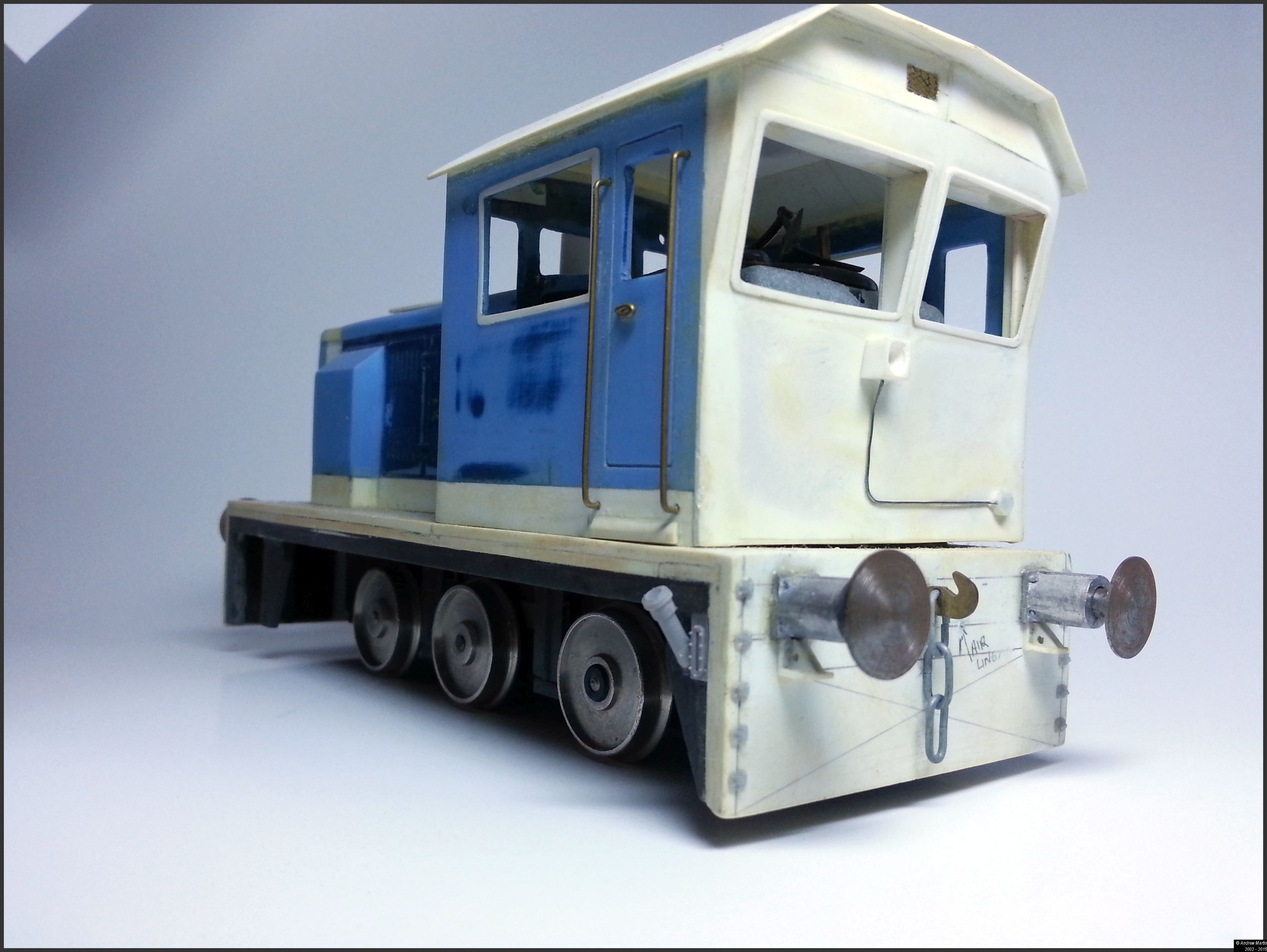
  • The three link couplings are also working with draw gear behind them on the front and the back. Finally the electrical junction box is a 1:48th MU cover glued on to the face.
  • Finally the window frames are all 20 thou and allow a 0.5mm overhang into the window space. I am hoping to get some microscope slide covers cut and put in place in all of the windows. Should that prove too bothersome I will cut out some Monitor protector plastic that I’ve saved from work and use that in its place. It will be secured in either case by Revel clear cement.
Photo 4: The front of the loco
Photo 4: The front of the loco_

It’s getting late, so I’ll just add a couple more photos. If you have questions let me know in the comments and I’ll answer them for you.

20150205_171618
Photo 5: A 3/4 view of the front of the loco


I’m not sure if I am going to leave the running gear showing like this or turn it into a tram loco. But the tram idea has me in its grip at the moment.

20150205_171154
Photo 6: Rear left 3/4 view showing the fuel filler and tank gauge


The fuel filler and gauge are from a 1:48 scale add on kit I’m using on my GP38-2 rebuilds.

Well – that’s it for now. Talk to you all later.


Site seeing – April 1st

No April Fool’s here!!!

Today’s site seeing focuses on what I consider to be the best Australian freelanced, yet believable, model railroad system – the Dutton Bay Tramway. The only other narrow gauge line I can thnk of in the same league is Dave Frary & Bob Hayden’s ‘Carrabasset and Dead River’ that has as rich a heritage. read on, there’s a lot in today’s site seeing that you might find as fascinating as I do.

Site 1: The Dutton Bay Tramway (Link Here)

The Dutton Bay Tramway was a freelanced HO scale 2’6″ gauge railway set in South Australia’s Eyre Peninsula. I say was because at this time the layout has been dismantled and in storage since December 2010, with no one looking to take over the layout and erect it in a new home.

Picture 1: Loading the final Gypsum train at Kelvin (Source: Railpage)

The work of John Dennis and Peter Knife (primarily) the roots of the DBT started in 1968 when the two friends built a narrow gauge layout in John’s bedroom at his parent’s home. For the next 20 years life happened and the layout ebbed and flowed in their lives until in 1988 Peter Knife made the commitment to display a narrow gauge layout for the Liverpool NSW exhibition.

Having started life as an exhibition layout The DBT has a long history after that first exhibit in 1988. The DBT layout retired from the exhibition scene after the Adelaide Model Railway Exhibition of June 2001. It travelled to most of the major state capital cities during that time (which is no mean feat).

John Dennis then set up the layout permanently in his home until operations ceased in 2010.

Why I like the DBT

There is a lot of thought and history behind this model railway. It exists in a place, has a history of its own, a reason to exist, customers to serve and a purpose to fulfil. It shows in the modelling, often taken from real locations and similar circumstances and as someone who has followed the layout in all its guises for many years in print and online I felt sad to see it go. I had an emotional attachment to the railway system. I would have rail-fanned it if given the chance.

I may yet, in some guise, make a model of the line as a tribute to both Peter and Dennis’ commitment to great modelling.

With imitation the most sincere form of flattery there could be no greater form of foolishness, on the day of fools, than to build a model railway of a model railway which set the standard for me when it came to developing a compelling and believable layout.

How this all applies to my modelling

In the past the Hunter Valley Lines has had many articles written, but not published on its history, the political influence and situational awareness of the industry bought about by changes in the Australian Railway landscape. I do not pretend to be a railway expert, but I do believe that the HVL had a development cycle as believable as I could make it, given the experience and the knowledge I gained from living in the USA for 10 years, and that this has been applied to the models I build and the layout I am building now.

Resources

Print:

Australian Model Railway Magazine

  1. Dutton Bay Tramway AMRM #237 December 2002 17 Article Dennis, John
  2. Dutton Bay Tramway AMRM #284 October 2010 16 Article Dennis, John

Images:

John Dennis’ album (via Photobucket) showing most of the last op session shots or view the embedded item below

http://s164.photobucket.com/user/duttonbay/embed/slideshow/Dutton%20Bay%20Tramway

Video:

Dutton Bay homepage:

Google search:

  • Click the link here to see the full search results

Site seeing – March 31

If you’re a regular reader of the blog, you’ll know that I’ve had some health challenges in the last week. It is perhaps fitting today, for the last day of March, that we look at objects other than me in need of repair.

I love a good wrecked model railcar, especially when they’re done right. Unfortunately scaling down a wreck is not easy. Plastic is not steel, especially in scale and so plastic tends to be an order of magnitude thicker than steel would be in a scale model. Getting it right is more an art form than a science. Which leads us to today’s sites…

Site 1: Model railroad hobbyist forum (Link here)

Over on the MRH Forum there’s a thread running on ‘Train Wreck Experiments with a heat gun and weathering’.  I really like the work that went into this unit. And there’s some great advice on modelling wrecks from those in the know on this thread.

Site 2: Model railroad hobbyist forum (Link here)

Also on the MRH forum is another thread at the moment on dents and dings on cars. There are some reall good comments starting to come out in the conversation, and some great pictures as well like this one by Verne Niner:

Read on for some more great ideas.

Site 3: Jeff Eggert’s Yard Office (Link here)

I’ve vistited Jeff’s website again, and again, and again. His scratchbuilt grain hopper (linked here) is a masterpiece, and in line with today’s dent, bent and rent theme. I hope that you enjoy.

Talk to you again in April.

I made some ties

Chris Mears over, on the Prince Street blog, spent some quality time recently ripping out Balsa ties for his railroad.

I bought one of these tools a while ago to make ties for my future O gauge layout (also using Balsa). A big thanks to Chris though for simplifying the idea for me.

Chris Mears's avatarPrince Street

DSC01617

Armed with a fresh sheet of balsa and my trusty balsa stripper, I have just finished making up one heck of a pile of ties. The process couldn’t be simpler. I’m starting with balsa sheet. Instead of cutting individual ties to length, I find it easier to cut the sheet to length, matching the length of my ties. I can then rip these into individual ties using the balsa stripper. Since the tool manages the width of each tie, the only really careful work is dividing the sheet by length. In all, I find it relaxing work. I figure I cut about a thousand ties this evening and this brings me another step closer to getting some track in place.

View original post

Kidney stones – I must have rocks in my head

Wednesday morning, 1:00 AM and a call to the ambulance because I thought my appendix had ruptured. Unfortunately I was not that lucky. The result, after 3 days in the hospital, is I’m stabilised, but have further surgery to get through (in just on 4 weeks) to hopefully break up the kidney stones .

For the next few days I’m going to be taking it easy, I’m still quite sore, but expect to see more posts in the next couple of days.

Thanks for reading the blog and I’ll be back with you again soon.

Regards

Andrew Martin

Site seeing March 24

I’ve followed Richard’s layout efforts for a while now on YouTube as he has built and modified Everard Junction. He’s not modelled a location, or an era, or a specific set of locomotives and wagons, he’s managed to capture the complete railway experience. And while Everard Junction is not a real location, it sure feels like one.

Site 1: Everard Junction – BR 1988 – 1990 (Link Here)

Richard started building the layout in late 2009 and has worked on it ever since. His aim was to create something reliable as his earlier layout had very poor track work and caused issues every time he used it. Everard Junction was to be bigger, reliable and above all he wanted it to be fun to operate.

Details

  • Era – British Rail sectorisation in the late 1980s.
  • Location – Somewhere not far from the great western mainline with connections to Reading, Didcot, Bristol, Bath and Birmingham
  • Stock – Diesel locomotives and DMUs of the period

He most recently published a great British Rail styled 1980’s PR video which you can watch here:

There are a range of very useful and thoughtful videos available on Richard’s YouTube channel (see the link to that below). Well worth a watch as he builds the layout and makes Everard Junction a real slice of railway operations.

Resources:

Site seeing March 23

Among the best forums to be on for new US small layout modelling is the USA and Canadian forum over on RMWeb (Link Here). There’s always someone building a layout for a show, or home and the ideas simply keep on coming.

Site 1: 59th and Rust (Link here)

Today’s site seeing adventure belongs to one that I’ve followed for some time by Ray (Long Island Jack) – 59th and Rust. What I really enjoy is his sense of urban rust and decay. Too green for me, as I’d like to see a lot more brown grass and stubs, but never the less, what a great work of art.

Enjoy the videos that show the basics of a switching session, again about the 20 minute mark, and enjoy those Alco sounds. Now if only we had some Alco diesel smoke…

In this first video a PC RS-11 is switching Goldberger Doll

In this video the PC RS-11 is switching Tino Tools

All the best for the evening from a cooling (it was warm 5 minutes ago) and windy Ballarat.

Site Seeing March 22

Bound for South Australia

Small, smart, practical exhibition layouts are not as easy to find as I’d like in Australia. Most club layouts are huge affairs, requiring many willing hands, a box trailer or van, and a pioneering spirit to move from home to exhibition to home.

Site 1: “Commercial Road” – 1960s South Australian Railways (Link Here)

One such layout that just popped up on my radar on Thursday is the Commercial Road layout of Gavin Thrum of South Australia. If you’ve not come in contact with the railways of South Australia before then you are in for a real treat.

Commercial Road – view the website for more great pictures of the layout

The South Australian railways are an interesting study in Multiculturalism. Originally built to English standards,  and operating practices, in 3 gauges (Irish Broad at 5′ 3″, Standard Gauge at 4′ 8 1/2″, and Narrow Gauge at 3′ 6″) the states rail system was a hodge-podge of types and wooden bodies goods and freight wagons until 1922 when the state’s worst financial deficit reared its ugly head.

To the rescue rode Commissioner William Webb (of the Missouri Kansas and Texas RR) and from 1922 Mr Webb revolutionised railroading in the south.

Engine 502 – 1953 – Public Domain Image courtesy of Wikipedia (more detial below)

Speed signalling, large steam engines, metal freight cars, Brill railcars, and more became the norm. Today there are still three gauges in use and lots of action through the state and in Adelaide where electrification has finally arrived (link here); Very similar to the Victorian VLocity diesel railcar (link here) that I travel in down to Melbourne. (I love electric traction)

But I digress; back to the layout. It’s a great small layout measuring 10′ 10″ long by just 13″ wide. Hop on over to his site and take a look at the images and the modelling. Really well worth a visit.

Resources

Wikipedia article on the SAR – Link Here

More on the big steamers of the Web Era

Why I chose not to design my layout – Part 5

Somewhere back in a previous post I am certain that I published a basic op session. Today I wanted to update that in light of the new layout design, as there is a pretty big change to both the ops plan and the layout since I first set track on plywood.

A Modified Op Session

An op session will start where ever the previous session stopped. You should keep in mind that I am aiming to have roughly one 30 minute operating session per night, at least 3 nights per week. I’d like more but the realities of work and family mean that aiming for 3 nights is achievable.

Assuming that a full day’s work (around 90 minutes odd) is planned for say a Saturday op session here’s how the work would be done.

The yardmaster will go through the electronic system (more about that later on) and determine what cars are due to be picked up and what inbound cars are due to be setout for the day. The YM then hands the paperwork off to the switch crew and goes about his business.

We pick up with the switch crew after they’ve already travelled out to the interchange, connected on, pumped up the air and begun their return back to the Industrial park.

  1. Train arrives from interchange
  2. Loco runs around the train on the arrival track and moves the train over to the classification 1 track
  3. Cars are classified according to the switch list using the main, loop and the Class 2 track
  4. The crew checks the pickups and setouts for industries and then sets about doing the individual jobs for each customer. In cases where there are multiple customers on a spur, the job is handled as a single job
  5. Industries are pulled and setout as required by the switching documentation
  6. The crew then returns outbound cars to the yard, for storage while other switching goes on for other customers (if any that day)
  7. Once all of the industries for that day are switched all outbound cars are made up into a train (blocking is not required)
  8. The final work for the day is to pull the outbounds to the interchange
  9. The cars are set out, handbrakes applied as needed and the air bled off
  10. The loco crew return empty handed to the yard, carry out any further trimming of the class tracks as needed, and
  11. Run the loco back into the maintenance facility.

Here endeth the operating session.

As I said above this full operating session ought to take up about 90 minutes. Allowing the session to be broken down into shorter, easier to achieve 30 minute mini-sessions means I’ll be more likelt to play with my layout, and get more enjoyment from it.

Between sessions the paper work will be hung on clip boards off the front of the layout ready for me the next night.

Should I want to run a longer session I can do that and simply complete the previous sessions work as a part of that.

Why I chose not to design my layout – Part 4

I did some measuring on the new track plan (version 3) today and the result is pleasing (at least to me). On the HVRR we use a XAF10 Railbox car as our standard measure for cars; These car’s measure 190 mm over coupler faces – that’s right on the 54′ and some change that a real car has for door spacing if it is recorded as a 50′ car. With the numbers in hand I tried a few calculations to see how everything fit.

Yard Tracks

With measurements now completed on all of the storage and “yard” tracks our holding ability on all tracks suggests that the:

  • Main (at 1400 mm) can clear 7 standard cars,
  • Loop (at 1500 mm) can clear 8 standard cars.
  • Classification track 1(at 1800 mm) can clear 9 cars ,
  • Classification track 2 (at 1300 mm) can clear 6 cars, and
  • The total on-track yard capacity is 30 cars (not including the interchange as I consider the interchange loadings to be a part of this number).

Yard Occupancy

I don’t want to flood the yard on any one day so I expect that the total yard occupancy at maximum will be 50% of the total – leaving me with 15 cars maximum. So that even with a full train of 9 cars coming in from the interchange I can use Class 1 & 2 to store all of the cars and leave the main and the loop free to work. More on this though below.

Industry tracks

On the main board there are two industries:

  • Industry 1 is 800 mm long and can manage 4 cars
  • Industry 2 is 1600 mm long and can manage 8 cars
  • Interchange track (at 2400 mm) can clear 9 cars plus the loco. The interchange track is considered an industry also.

The trackage on the base of the L are to be built based on an article in Model Trains International #58, page 106 by Bruce Petty. While this was essentially an article on scratchbuilding the Strongheart Packing Co. there was also a track diagram included. While I cannot post the magazine article here for you, I can point you to Bruce’s website which has the same information and track diagram (link here)

The current track layout in this area bounded by East 49th and E 50th Street is somewhat different from that of 25 – 35 years ago, this is reflected in the two images here:

Strongheart Packing Co - Vernon CA

Image 1: Block bounded by 49th & 50th Street, and Gifford To Corona Ave

This is an overhead view of the same block as in the article, but several of the buildings have been removed; specifically Union Malleable and Strongheart Packing. Otherwise the track for the most psrt seems to be intact.

Vernon CA - 49-50th Street - Gifford to Corona Ave - Track Layout

Another overhead view showing a slightly different angle that puts the article map in perspective.

I’ll be leaving building’s in place at Ingle Bros. It is a nice, generic building, plain brick that will be easy to model. It will have the two car spots as on the plan. The Chase Bag Co will go. In it’s place I’m going to put a team track. This will ensure that I can have a range of cars in that spot, and in addition give a great view of the remainder of this section of the layout.

The other buildings will be changed slightly to give that 1970’s renewal look of tilt-up concrete construction so prevalent in Texas.

Industry occupancy

Just as for the yard, I do not want to flood the industry tracks with cars. There are two reasons for this:

  1. I like that industries are not always blocked with cars – this is also very prototypical, and
  2. I am aiming at maximum to have industries be 50-60 percent occupied

Thus the total car numbers of the main board will be:

  • Industry 1 holds on average 2 cars with a maximum of 3 cars
  • Industry 2 holds on average 4 cars with a maximum of 5 cars
  • Interchange holds on average 5 cars (rounded up from 4.5) to 7 cars.

As noted earlier it can clear up to 9 cars at any one time if needed; this ensures that the interchange and the yard tracks should never be flooded with cars to stop the operations of the railroad.

The industrial park (bottom of the L) boards will hold on average 7 cars using the same occupancy rate. In total then the maximum cars in and out of the layout (should all of the occupied spots be switched on one day) would be 17 cars. Luckily that is not going to happen because these car movements would be spread over 6 days.

I am hoping the average will be in the range of 4-5 cars per session. This meets my goal of a short switching session, but with plenty of interest for me as the crew. More on this later.