Been a busy modelling weekend in Ballarat. I’ve added a new page to the modelling articles section about my rolling stock standards. You can find the Rolling Stock Standards page here.
I wrote this after reading Dennis Storzek’s excellent article from 1982 (I recently found a copy in a bargain bin in one of Melbourne’s bookshops) for the club I belonged to at the time. I’ve reworked the document over the last couple of days to allow you to use this for your club (if they do not have a modelling standard) or for yourself if you need one as I do.
Grab the PDF here. The document is copyright, but released under a Creative Commons license. Read more about that in the PDF. Happy modelling and let me know if you come up with any improvements.
It’s a first for me; I’m building two Victorian Railways GY grain wagons from the excellent Steam Era Models (SEM) kit. Apart from the excellent moulding you also get photo-etch for a nice price (in the Australian market) of $17.50.
Most of the build focuses on upgrading the underframe, paint and weathering; there is little about the kit that needs work. This will be a multipart article. Part 1 is online now.
In light of yesterday’s ‘Ultimate DCC Throttle’ project by Bruce Kingsley, I thought that I’d show you a simpler, and more easily achieved project from some time ago by nwbatman2222. The information on the project is unfortunately light; making the changes should not be too hard, but would need soldering skills to change your hand-held controller of choice.
Site 1: Switching with a Control Stand throttle
It is a shame that there is not more information available from the maker. However, looking through the notes in the video there are some hints about what is needed to make this a reality.
If you do come up with a means to reproduce this would you share it with me? I’d like to make one of these with my handheld (I’m using MRC’s Prodigy Advanced 2) but I don’t want to completely ruin a handheld at the moment. If I could get a second-hand one or a complete system on the cheap then I might be more willing to have a go.
Site 2: Tsunami Non-Turbo EMD 645
Video two shows everyday use of the throttle, again clamped to the camera to allow you to see the action. Once you got used to handling the loco like this driving would be a more enjoyable proposition.
If you have any information on the layout owner or on the handhelds please drop me a line using the comment fields on this page or using the Contact Form for this site.
I hope that you have enjoyed the videos, and the idea of the different throttles. All the best for a great day ahead.
DCC (Digital Command Control) has changed the way we interact with the our model railroads. We no longer drive the track, or the single locomotive on it, now we drive our train. Just like the real thing we can now have corn field meets, SPADs (signals passed at danger) and other issues that DC powered layouts never had to deal with.
In the next 10 years the way we look at DCC will change too, indeed it already has. We now have DCC and sound, we have the beginnings of DCC sound and vision to go along with it. Soon though we’ll be offered the immersive nature of these working together, to totally immerse the driver or engineer, in the model railroad experience. Think of the difference that this will make for those operating in the garden, or for those on smaller layouts. That is what today’s site seeing will give you a glimpse of.
Site 1 – Bruce Kingsley – Ultimate DCC Throttle
Bruce’s project is audacious. I admire his scope, and the work he has put into the project. It is not for me, although if I could buy one commercially I would certainly consider this in the future.
The beginning of the video through to 3:20 minute mark is a little dry; from that point on however it is very enlightening and entertaining.
He has a lot of videos about the UDCC throttle. If interested in the technology behind it all you should take a look through the rest of his videos. He provides a lot of notes on the parts used to get his set up running. I’ve not visited his website; there is sure to be more there for you to learn.
On June 02, 2015 I made mention in a post of a grain silo operation close to the CBD in Melbourne, Victoria that allows for interesting operation, and would keep a model railroader busy and interested for the length of a short operating session (around a half an hour).
Image 1: G529 stabled in the dead-end siding at Kensington. The grain hoppers and the switch engine are down by the flour mill (courtesy of wongm’s rail gallery – LINK)
A little background
For those of you not in Australia let me give you a little background on the site from image 1 above. The photo above is from the grade (level) crossing at Kensington station. The station buildings are directly behind the photographer. G529 is sitting at the north end of the site on a dead-end siding used for second units or for red-carded (bad-ordered) cars.
The two lines under wire are the UP (left-hand line to Melbourne) and the DOWN (right-hand line from Melbourne) lines to the outer suburban terminus of Craigieburn, a fast growing suburb 26 Km to Melbourne’s north. Grain trains come north from Tottenham Yard and back into the sidings. When they leave they have to do a long looping route north, then west before returning to the yard once more. A fair bit of this is on the suburban Craigieburn passenger line. This situation occurred because of changes to rail lines for the Regional Rail Link that has taken freight lines out of service.
The single slip allows access into the site from the DOWN line. On the mill site there are two spurs with the left road running over the under track unloading auger; the right is a passing siding. The switching problem on this site is that the turnout at the end of the two roads only has enough room for two grain cars, and one locomotive at a time.
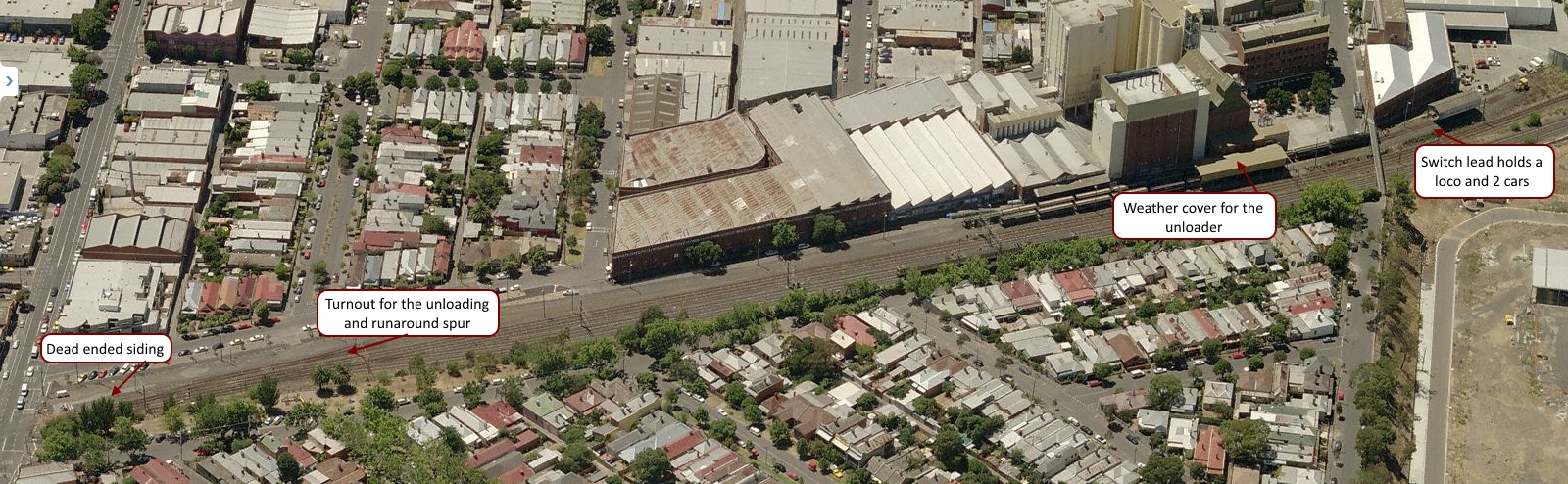
Image 2: An overview of the site (courtesy of Bing – LINK)
Operation
Generally the train has two locomotives. While a single locomotive can handle the work, and would be easier on the crews when switching, the extra power helps clear the path for the passenger services on the Craigieburn line. Melbourne’s rail network is greatly used by the it’s citizens and the infrastructure is congested requiring new signalling to allow greater train density. Anything that holds up one train has knock-on effects that can and do regularly impact on the rest of the network. So any freight movements using passenger routes tend to be over-powered.
Image 3: A track diagram showing the grain siding and signalling at Kensington (courtesy VicSIG)
1. Arrival
The shift begins with the loaded grain train arriving early on the north-bound suburban tracks. The train pulls into Kensington stations up platform road, before informing train control that they are ready to reverse into the facility. Train control (under CTC) unlocks the shunt signal 7, switch 8 and switch 9 to allow the movement and the train reverses into the site, putting the grain cars onto the ‘left-hand’ unloading road. On completion of the move the crew contacts train control once more and the switches and signals returned to normal.
2. Set up
The crew has to unload one of the locomotives. Without the room to run the power around at the switching end on the unloading road one loco is usually parked on the ‘B’ siding at the north end of the site. Image 2 below shows the problem on-site with the short headshunt (switching lead).
Image 4: The switching problem – the short headshunt (courtesy of wongm’s rail gallery – LINK)
3. Switching / Shunting
Prior to unloading beginning the mill staff remove the metal grate covers to allow grain to begin unloading into the under-track auger. With only one loco for shunting (switching) the operation is fairly straight-forward:
The first two cars unload at the under-track auger
When unloaded the train pulls forward to two car lengths to begin the unloading process again and handbrakes are applied
The loco cuts off the two empty cars, pulls them to the headshunt, before pushing back onto the passing siding
Handbrakes are applied on the two empty cars before the loco cuts off and moves back to the headshunt
The loco reverses onto the loaded cars, and the cycle repeats until all the cars are empty.
With all the cars emptied the mill workers cover the auger pit with the metal covers. The loco eases off the unloaded cars, runs into the headshunt, and backs through the unloading road back to siding B. Here it picks up the previously stabled locomotive and once MU’d they back onto the empty cars; with the air pumped and they wait for train control to authorise their return to the running lines.
Modelling
Operation of this layout design element offers a lot of opportunity. Whether a small train or a large one the work to be done, including air brake operations and taking time to switch back and forth would give a lot of interest for those so inclined. I can see this being a great industry especially for the modular railroader. Across two or more modules, you’d have the best of all worlds with action on the main, and then a lot of switching action on the modules.
Being self-contained the industry is a real winner and could be transplanted anywhere.
Resources
There are a couple of videos available below for you to get an idea of the action at Kensington.
In the second video you can see the operation under way with the switching in this case being handled by BL class # 32.
You can find out more about the locomotives using the resource links below:
If you have information that you can share about operations at the site, please let me know. I’ve found everything that I can about the site and its operation, but there is nothing like a driver or someone else knowledgeable of the site sharing what they know. Leave a comment, like and subscribe to the blog if that suits you.
I love signalling, and modelling signalling systems. In the future I have a plan for an exhibition layout running under catenary, fully signalled using automatic block signals. For now though the plan is to get the current layout done.
In the meantime we can all enjoy some great old video – thanks to YouTube.
Site 1: YouTube – The Railroad Signal by the New York Central System’s PR Department
I love these old videos and collect them when I can. This one is great, and shows a lot of features of the steam era railroad that you might not otherwise notice.
While I chose not to (over) design my layout, there are some aspects that simply have to have a structured and logical approach to simplify troubleshooting for the longer term. These need to be in place to allow me to add to and grow the layout in the future. This post focuses on the wiring standard for all layouts that I build going forward.
After watching the current work being done over at Everard Junction with the wiring of the new section of his layout (+ Link) one of the things I noticed was the colour code in use. I feel that in the future he’ll find that there’ll be more stress and confusion in the future when tracing and troubleshooting.
As a former telephone technician colour codes are very important to me. As a result I’ve written a module / baseboard wiring standard. If you are not worried about troubleshooting your wiring in the future you can ignore this post now. Each module / baseboard will have a dual wiring BUS. One BUS will power the Locomotives and DCC accessories (the DCC BUS) while the other will power the DC accessories and other non-DCC devices (the DC BUS).
You might be wondering why I’d have non DCC accessories. Think for a moment of LED lighting. LED Lighting is 12V DC so lighting the module / baseboard is made easier using the 12 volt BUS. Additionally internal building lights, signalling and repeater panel lights that do not use DCC to operate can be powered off this BUS. Finally there is no extra effort required to wire these up later; its wired into the module / baseboard from the get-go. There’s no extra work to get DC powered items wired up beyond setting up dropper wires to the DC BUS.
The wiring standard for the boards and modules is a work in progress. You are welcome to download version 1. Please keep in mind it is not in the public domain. You may use it for personal use only. Any commercial applications of the document should be run by me first.
I don’t claim that this is the standard you should be using; it works for me. If it works for you too, then please download and use it.
The costs of buying sheet styrene has gone up a lot recently. Let me say that I love my Evergreen styrene; I could not model what I model without them. I recently updated and added to my modelling stash of shapes for upcoming projects. Luckily I found a local supplier who is among the cheapest in Victoria for Evergreen.
However, when you need a lot of sheet styrene buying multiple packs of 40 thou (1.0 mm) and 20 thou (0.5 mm) styrene gets expensive very quickly. A business friend bought the local plastic company here in town a couple of years ago and he has these thicknesses of styrene I use most often (called HIPS in the trade in Australia) available in 8′ x 4′ (1200 x 2400 mm) sheets. At around $A22.00 for that size of 20 thou sheet and double that for 40 thou sheet you can see that there is some serious savings to be had buying that way.
Dale, the owner of General Plastic in Ballarat, is always helpful to modellers and a lot of modellers use his services to get what they need in the Western Victorian region. Dale has a full set of products and can get whatever you need. More importantly Dale has added a Laser Cutter and can cut whatever you need directly from your CAD file. If you live close by drop in and say hello.
Site 2: Harper’s Hobbies and Collectibles [+ Link]
Harper’s’ Hobbies in Wendouree is becoming a really great place to visit. Ballarat is not short of good model sellers. What makes the difference is that Harper’s has the basics you need to scratchbuild, along with a really good tool choice. That makes a difference. Also they have begun to stock the Warhammer 40K range of kits that my son is right into.
While the sites are really Western Victorian focused today, perhaps you’d like to share your favourite modelling suppliers. Leave a comment and share.
Takeaway
If you buy larger sheets of styrene, one big problem is storage. Here’s what I do:
Cut the sheet into 4 pieces across the sheet with shears of large scissors
Using plastic clamps, join all four sheets to keep them under control.
That way when you need it you simply cut off what you need, and then rehang the remaining pieces.
As I mentioned in yesterday’s post my site hosting company is changing a lot of their backend stuff around. And that is causing all sorts of issues with the gallery. I’ve already moved all the posts from the old blog to here.
Today’s site seeing is about the beginning of that moving process.
My small layouts gallery contains layouts that are no larger than 16 square feet. Some are 8′ x 2 foot, others are longer but narrower. Enjoy taking a look around the layout designs. They’re all designed to be operated, and most have text on the image to help you understand the design. I’ll be updating the individual layouts over time with a suggested operating instruction set.
Due to my hosting provider changing a bunch of stuff on their backend, the main website of the HVL (HunterValleyLines.com) and the gallery (HVL Gallery) are going away. The website will be there, but the content will not be.
As a result of the changes I am going to begin to move all of my image content, and photo content over from the old site to this blog over the next couple of months. I’ll put these in the gallery section here on the blog, and upload as I go, letting you know when they are all online.
First to move will be the layout designs as these are still getting the largest number of hits on the gallery. I might even get around to writing all the operation plans for the layouts as I said I would all those years ago. If only days were 48 hours long, I’d get so much more done.